Tag Archives: motor

China 100KPa 370 dc 6v suction pump vacuum diaphragm motor air pump

Warranty: 1 year
Customized support: OEM, ODM, OBM
Model Number: JQB2438 – 1
Application: Electronic blood pressure meter, Medical monitor, Massager, Aromatherapy machine, Coffee machine
Horsepower: Consulting service
Power Source: Electric
Pressure: 0-120kpa, <120Kpa
Structure: Diaphragm Pump
Cable Length: Consulting service
Outlet Size: Consulting service
Voltage: DC3.0-24.0V
Power: 2.4W
motor: Consulting service
Air Flow: 3.5LPM
Port: HangZhou

Specification

ItemAir pump
Brand nameTCS
Model NO.JQB2438-1
Place of OriginHangZhou,China
Application Electronic blood pressure meter,other,Toy
HorsepowerConsulting service
Power SourceElectric
Pressure <=120Kpa
StructureDIAPHRAGM PUMP
Outlet SizeConsulting service
Voltage DC3.0~24.0v
Power2.4W
CertificationREACH&ROSH
Flow <3.5LPM
Noise<60DB
Life test300 hours
Environment0-50℃,75% RH
Company Profile Founded in 1996, HangZhou TCS Technology Co., Ltd. is located in HangZhou, a beautiful coastal city in ZheJiang , China.It covers an area of about 10,000 square meters and employs more than 600 people. It is a high-tech enterprise integrating R&D,design, production and sales. The company has passed ISO9001, ISO14001, TS16949 system certification, Fashion Stainless Steel Bracelet Jewelry 316 Franco Double Layers Wheat Link Chain Men Bracelet For Men and was awarded “HangZhou High-tech Enterprise” and “National High-tech Enterprise”. The company mainly develops and produces micro-motors, micro-pumps, pumps, solenoid valves, water valves, electromagnets,precision gearboxes, precision geared motors and high-precision parts. Products are widely used in medical equipment, household appliances, beauty care, water applications, robots, drones, automobiles and other fields. Based on the domestic and overseas markets, the products have established good cooperative relations with many well-known international companies. After more than 20 years of exploration and expansion, the company has become increasingly mature. The R&D team respects science,dares to explore and dares to innovate; is committed to product design innovation, production process automation, quality control and intelligentization, customer demand customization; Pto shaft adaptor wide angle U joint universal agricultural machinery tractor gearbox gear box drive shaft power take off high quality products and excellent service to win customer satisfaction. The above is part of the air valve products, more products including air pump, water pump, water valve, electromagnetic pump, electromagnet, reducer motor, please click the home page to browse, or consult customer service. Product Manufacturing DetailsWe have dozens of automatic machines and semi-automatic machines, through precise machine work and manual inspection, to ensure quality Corporate sectorWe work in good order, strictly in accordance with the factory rules, friendly cooperation, with the best attitude to serve customers, welcome to consult Manufacturing Technique Artificial partialDetection of dustSemi-automatic instrument SHIPMENT If you need any favorable or fastshipping welcome to contact us. Packing & Delivery To better ensure the safety of your goods, professional, environmentally friendly, convenient and efficient packaging services will be provided. FAQ 1. Q:What can we do for you? A: We can develop new products for you or modify parameters such as flow, current and pressure on existing products. We can OEM, ODM.2. Q:How can we guarantee quality? A: We have a perfect quality control team and process by fully inspecting the shipped products.Professional testing equipment.Strict life testing3. Q:Is it OK to print my logo on this product? A: Yes. Please inform us formally before our production and confirm the design firstly based on our sample.4. Q:What is your terms of Payments ? A: T/T,L/C,PAYPAL, Other payment methods are also available, please contact us before payment.5. Q:How long is thedeliver[Producing] and shipping ? A:Batch orders will be shipped in 25 working days. Sample order will be shipped within 3-7workingdays.6. Q:Are you a factory or a trading company? A: We are professional manufacturer and trader. The factory has 5 buildings with a total area of ​​more than 40,000 square meters. We warmly welcome customers from all over the world to visit and cooperate with the factory.7.Q: How long is your products quality warranty? A: We provide 1 year factory quality warranty.

Vacuum Pump

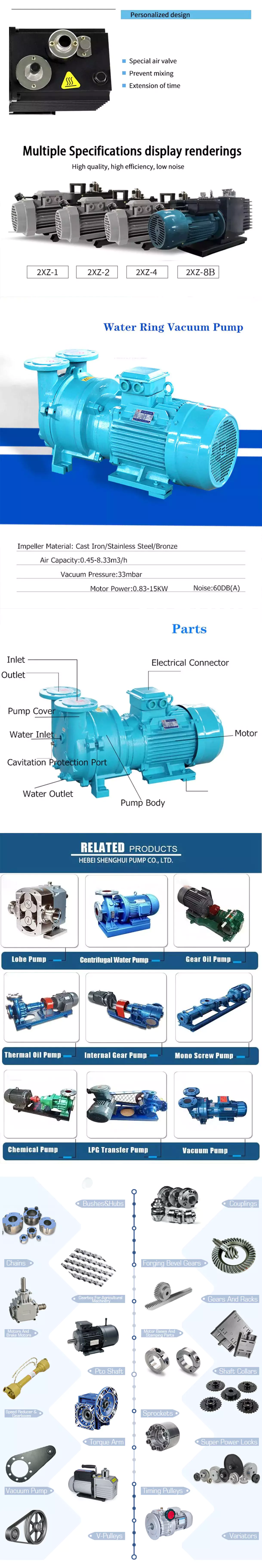
Basic knowledge of vacuum pump

A vacuum pump is a device that draws gas molecules from a sealed volume and maintains a partial vacuum. Its main job is to create a relative vacuum within a given volume or volumes. There are many types of vacuum pumps. This article will describe how they work, their types, and their applications.

How it works

A vacuum pump is a mechanical device that removes gas from a system by applying it to a higher pressure than the surrounding atmosphere. The working principle of the vacuum pump is based on the principle of gas transfer and entrapment. Vacuum pumps can be classified according to their vacuum level and the number of molecules that can be removed per cubic centimeter of space. In medium to high vacuum, viscous flow occurs when gas molecules collide with each other. Increasing the vacuum causes molecular or transitional flow.
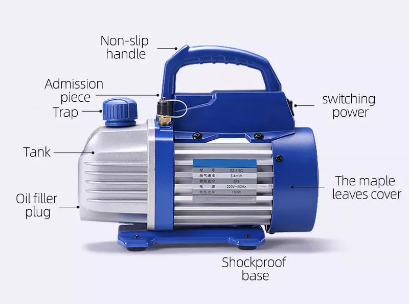
A vacuum pump has several components that make it a versatile tool. One of the main components is the motor, which consists of a rotor and a stator. The rotor and stator contain coils that generate a magnetic field when excited. Both parts must be mounted on a base that supports the weight of the pump. There is also an oil drain that circulates oil throughout the system for lubrication and cooling purposes.
Another type of vacuum pump is the liquid ring vacuum pump. It works by positioning the impeller above or below the blades. Liquid ring pumps can also adjust the speed of the impeller. However, if you plan to use this type of pump, it is advisable to consult a specialist.
Vacuum pumps work by moving gas molecules to areas of higher or lower pressure. As the pressure decreases, the removal of the molecules becomes more difficult. Industrial vacuum systems require pumps capable of operating in the 1 to 10-6 Torr range.

Type

There are different types of vacuum pumps. They are used in many different applications, such as laboratories. The main purpose of these pumps is to remove air or gas molecules from the vacuum chamber. Different types of pumps use different techniques to achieve this. Some types of pumps use positive displacement, while others use liquid ring, molecular transfer, and entrapment techniques.
Some of these pumps are used in industrial processes, including making vacuum tubes, CRTs, electric lights, and semiconductor processing. They are also used in motor vehicles to power hydraulic components and aircraft. The gyroscope is usually controlled by these pumps. In some cases, they are also used in medical settings.
How a vacuum pump works depends on the type of gas being pumped. There are three main types: positive displacement, negative displacement, and momentum transfer. Depending on the type of lubrication, these principles can be further divided into different types of pumps. For example, dry vacuum pumps are less sensitive to gases and vapors.
Another type of vacuum pump is called a rotary vane pump. This type of pump has two main components, the rotor and the vacuum chamber. These pumps work by rotating moving parts against the pump casing. The mating surfaces of rotary pumps are designed with very small clearances to prevent fluid leakage to the low pressure side. They are suitable for vacuum applications requiring low pulsation and high continuous flow. However, they are not suitable for use with grinding media.
There are many types of vacuum pumps and it is important to choose the right one for your application. The type of pump depends on the needs and purpose of the system. The larger ones can work continuously, and the smaller ones are more suitable for intermittent use.
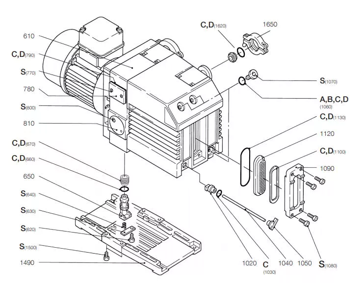
Vacuum Pump

Apply

Vacuum pumps are used in a variety of industrial and scientific processes. For example, they are used in the production of vacuum tubes, CRTs, and electric lamps. They are also used in semiconductor processing. Vacuum pumps are also used as mechanical supports for other equipment. For example, there may be multiple vacuum pumps on the engine of a motor vehicle that powers the hydraulic components of an aircraft. In addition, they are often used in fusion research.
The most common type of vacuum pump used in the laboratory is the rotary vane pump. It works by directing airflow through a series of rotating blades in a circular housing. As the blades pass through the casing, they remove gas from the cavity and create a vacuum. Rotary pumps are usually single or double-stage and can handle pressures between 10 and 6 bar. It also has a high pumping speed.
Vacuum pumps are also used to fabricate solar cells on wafers. This involves a range of processes including doping, diffusion, dry etching, plasma-enhanced chemical vapor deposition, and bulk powder generation. These applications depend on the type of vacuum pump used in the process, and the vacuum pump chosen should be designed for the environment.
While there are several types of vacuum pumps available, their basic working principles remain the same. Each has different functions and capacities, depending on the type of vacuum. Generally divided into positive displacement pump, rotary vane pump, liquid ring pump, and molecular delivery pump.

Maintenance

The party responsible for general maintenance and repairs is the Principal Investigator (PI). Agknxs must be followed and approved by the PI and other relevant laboratory personnel. The Agknx provides guidelines for routine maintenance of vacuum pump equipment. Agknxs are not intended to replace detailed routine inspections of vacuum pump equipment, which should be performed by certified/qualified service personnel. If the device fails, the user should contact PI or RP for assistance.
First, check the vacuum pump for any loose parts. Make sure the inlet and outlet pressure gauges are open. When the proper pressure is shown, open the gate valve. Also, check the vacuum pump head and flow. Flow and head should be within the range indicated on the label. Bearing temperature should be within 35°F and maximum temperature should not exceed 80°F. The vacuum pump bushing should be replaced when it is severely worn.
If the vacuum pump has experienced several abnormal operating conditions, a performance test should be performed. Results should be compared to reference values ​​to identify abnormalities. To avoid premature pump failure, a systematic approach to predictive maintenance is essential. This is a relatively new area in the semiconductor industry, but leading semiconductor companies and major vacuum pump suppliers have yet to develop a consistent approach.
A simplified pump-down test method is proposed to evaluate the performance of vacuum pumps. The method includes simulated aeration field tests and four pump performance indicators. Performance metrics are evaluated under gas-loaded, idle, and gas-load-dependent test conditions.
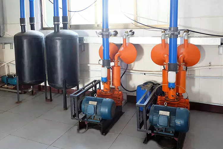
Vacuum Pump

Cost

The total cost of a vacuum pump consists of two main components: the initial investment and ongoing maintenance costs. The latter is the most expensive component, as it consumes about four to five times the initial investment. Therefore, choosing a more energy-efficient model is a good way to reduce the total system cost and payback period.
The initial cost of a vacuum pump is about $786. Oil-lubricated rotary vane pumps are the cheapest, while oil-free rotary vane pumps are slightly more expensive. Non-contact pumps also cost slightly more. The cost of a vacuum pump is not high, but it is a factor that needs careful consideration.
When choosing a vacuum pump, it is important to consider the type of gas being pumped. Some pumps are only suitable for pumping air, while others are designed to pump helium. Oil-free air has a different pumping rate profile than air. Therefore, you need to consider the characteristics of the medium to ensure that the pump meets your requirements. The cost of a vacuum pump can be much higher than the purchase price, as the daily running and maintenance costs can be much higher.
Lubricated vacuum pumps tend to be more durable and less expensive, but they may require more maintenance. Maintenance costs will depend on the type of gas that needs to be pumped. Lighter gases need to be pumped slowly, while heavier gases need to be pumped faster. The maintenance level of a vacuum pump also depends on how often it needs to be lubricated.
Diaphragm vacuum pumps require regular maintenance and oil changes. The oil in the diaphragm pump should be changed every 3000 hours of use. The pump is also resistant to chemicals and corrosion. Therefore, it can be used in acidic and viscous products.

China 100KPa 370 dc 6v suction pump vacuum diaphragm motor air pump    China 100KPa 370 dc 6v suction pump vacuum diaphragm motor air pump
editor by czh2023-07-03

China Custom Bus Parts Rear Axle Half Shaft for Electric Motor Drive Axle wholesaler

Solution Description

The illustration of Rear Axle


The Thorough Drawing of Described Rear Axle

Kind: Front AXLEAF 2.2~2.7                                                                                                   Variety: Entrance AXLE–AF 5.5

Application: 5~7 m Mentor/City Bus                                                                                               Software: 10~11 m Coach/Town Bus


Variety: Entrance AXLE–AF 75                                                                                            Variety: REAR AXLE–AR 40

Application: Over 11 m Coach/City Bus                                                                       Application: 5~8m Mentor/Metropolis Bus
Economic climate of The Axle and Suspension

In buy to improve the axle and suspension top quality, improve consumer car encounter, reduce following-revenue upkeep expenses, fully discover from domestic and overseas sophisticated axle technology, specifically in the axle wheel edge special innovation, from grease lubricated wheel edge, to oil lubricated wheel edge, and then to the maintainance totally free axle ans suspension wheel edge, when compared with the prior technology, there is a qualitative leap. Amid them, there are 2 sorts of routine maintenance-free wheel edge: oil lubrication maintenance-free (generally 500,000 km upkeep-free) and built-in servicing-totally free (specifically bearing unit, 5 a long time / 800,000 km maintenance-free).

Firm Profile

 DUOYUAN Automobile Products CO.LTD

Duoyuan auto gear, addresses an spot of more than a hundred acres and has more than 300 employees, including far more than ninety experts and specialized staff, more than 10 senior engineers, and a lot more than 30 intermediate engineers.

Our objective is to turn out to be the 3rd celebration professional automobile parts supplier with innovative spirit and top engineering. With constant design and development for 16 years, we have cooperate with YuTong Team for a expression method. Existing solution industry quantity: More than four hundred,000 items of bus specific axles, over 250,000 kits of bus air suspensions yearly creation capacity: a hundred,000 pieces of bus particular axle and 50,000 kits of bus air suspensions. In 2018, our sales exceeded RMB 1.5 billion.

At current, our products are primarily bus-oriented, providing matching products to total ranges of designs these kinds of as passenger bus, vacationer bus, group bus, community transportation bus, university buses and new strength bus Also, we are actively expanding truck and other professional motor vehicle marketplaces. Our products are bought to a lot more than 130 nations around the world and locations in the globe these kinds of as Cuba, Venezuela, Russia, Iran and Saudi Arabia as parts of comprehensive motor vehicle.

In buy to comprehend a far better future, we, by upholding the spirit of exploration, learn widely from others’ strong factors and soak up foreign and domestic sophisticated knowledge, and attempt for the development of China’s automotive tools.

FAQ

Q:Are you buying and selling organization or producer?

A: We are manufacturing unit who have been specializing in planning and production axle and suspension for 20 many years .
Q:Can your items be customized or modified?

A: We can layout and create the axl and suspension according to customers’ needs and car parameters .
Q: What is your phrases of payment ?
A: 100% Advance payment by T/T soon after signing the deal.
Q: What is your terms of packing?
A: Normally, we set buggy axle on Wood pallets,Stretch movie set in picket box . Or Buyer essential.
Q: How extended is your supply time?
A: Typically it is fifteen-25 times if the merchandise are in stock. or it is 35-forty five times if the goods are not in stock, it is according to
quantity.
Q: What is your axl sample coverage?
A: We can source the buggy axle sample if we have ready areas in stock, but the buyers have to pay the sample price and he courier value.You should speak to with me with buggy axle.
Q. Do you take a look at all your buggy axle prior to shipping?
A: Yes, we have one hundred% examination ahead of supply
Q: How do you make our company long-term and good romantic relationship?
A:1. We preserve axle and suspension a very good quality and aggressive price to make sure our clients gain
2. We respect every single client as our good friend and we sincerely do organization and make friends with them, no matter exactly where they occur from.

Suspension Model
AR115
 
 
Rated load(kg)
115000
Brake Type
Disc/Drum
Rim Distance(mm)
1832
Max out Torque(Nm)
30000
Distribution Circle
10*335
Flange Type
Plain Flange
Ratio
3.15~6.17
Applicable Bus
7m Bus
Wheel Hub Type
Bearing Unit
Weight(oil included)(kg)
690()Drum)/630(Disc)
Suspension Model
AR115
 
 
Rated load(kg)
115000
Brake Type
Disc/Drum
Rim Distance(mm)
1832
Max out Torque(Nm)
30000
Distribution Circle
10*335
Flange Type
Plain Flange
Ratio
3.15~6.17
Applicable Bus
7m Bus
Wheel Hub Type
Bearing Unit
Weight(oil included)(kg)
690()Drum)/630(Disc)

Driveshaft structure and vibrations associated with it

The structure of the drive shaft is critical to its efficiency and reliability. Drive shafts typically contain claw couplings, rag joints and universal joints. Other drive shafts have prismatic or splined joints. Learn about the different types of drive shafts and how they work. If you want to know the vibrations associated with them, read on. But first, let’s define what a driveshaft is.
air-compressor

transmission shaft

As the demand on our vehicles continues to increase, so does the demand on our drive systems. Higher CO2 emission standards and stricter emission standards increase the stress on the drive system while improving comfort and shortening the turning radius. These and other negative effects can place significant stress and wear on components, which can lead to driveshaft failure and increase vehicle safety risks. Therefore, the drive shaft must be inspected and replaced regularly.
Depending on your model, you may only need to replace one driveshaft. However, the cost to replace both driveshafts ranges from $650 to $1850. Additionally, you may incur labor costs ranging from $140 to $250. The labor price will depend on your car model and its drivetrain type. In general, however, the cost of replacing a driveshaft ranges from $470 to $1850.
Regionally, the automotive driveshaft market can be divided into four major markets: North America, Europe, Asia Pacific, and Rest of the World. North America is expected to dominate the market, while Europe and Asia Pacific are expected to grow the fastest. Furthermore, the market is expected to grow at the highest rate in the future, driven by economic growth in the Asia Pacific region. Furthermore, most of the vehicles sold globally are produced in these regions.
The most important feature of the driveshaft is to transfer the power of the engine to useful work. Drive shafts are also known as propeller shafts and cardan shafts. In a vehicle, a propshaft transfers torque from the engine, transmission, and differential to the front or rear wheels, or both. Due to the complexity of driveshaft assemblies, they are critical to vehicle safety. In addition to transmitting torque from the engine, they must also compensate for deflection, angular changes and length changes.

type

Different types of drive shafts include helical shafts, gear shafts, worm shafts, planetary shafts and synchronous shafts. Radial protruding pins on the head provide a rotationally secure connection. At least one bearing has a groove extending along its circumferential length that allows the pin to pass through the bearing. There can also be two flanges on each end of the shaft. Depending on the application, the shaft can be installed in the most convenient location to function.
Propeller shafts are usually made of high-quality steel with high specific strength and modulus. However, they can also be made from advanced composite materials such as carbon fiber, Kevlar and fiberglass. Another type of propeller shaft is made of thermoplastic polyamide, which is stiff and has a high strength-to-weight ratio. Both drive shafts and screw shafts are used to drive cars, ships and motorcycles.
Sliding and tubular yokes are common components of drive shafts. By design, their angles must be equal or intersect to provide the correct angle of operation. Unless the working angles are equal, the shaft vibrates twice per revolution, causing torsional vibrations. The best way to avoid this is to make sure the two yokes are properly aligned. Crucially, these components have the same working angle to ensure smooth power flow.
The type of drive shaft varies according to the type of motor. Some are geared, while others are non-geared. In some cases, the drive shaft is fixed and the motor can rotate and steer. Alternatively, a flexible shaft can be used to control the speed and direction of the drive. In some applications where linear power transmission is not possible, flexible shafts are a useful option. For example, flexible shafts can be used in portable devices.
air-compressor

put up

The construction of the drive shaft has many advantages over bare metal. A shaft that is flexible in multiple directions is easier to maintain than a shaft that is rigid in other directions. The shaft body and coupling flange can be made of different materials, and the flange can be made of a different material than the main shaft body. For example, the coupling flange can be made of steel. The main shaft body is preferably flared on at least one end, and the at least one coupling flange includes a first generally frustoconical projection extending into the flared end of the main shaft body.
The normal stiffness of fiber-based shafts is achieved by the orientation of parallel fibers along the length of the shaft. However, the bending stiffness of this shaft is reduced due to the change in fiber orientation. Since the fibers continue to travel in the same direction from the first end to the second end, the reinforcement that increases the torsional stiffness of the shaft is not affected. In contrast, a fiber-based shaft is also flexible because it uses ribs that are approximately 90 degrees from the centerline of the shaft.
In addition to the helical ribs, the drive shaft 100 may also contain reinforcing elements. These reinforcing elements maintain the structural integrity of the shaft. These reinforcing elements are called helical ribs. They have ribs on both the outer and inner surfaces. This is to prevent shaft breakage. These elements can also be shaped to be flexible enough to accommodate some of the forces generated by the drive. Shafts can be designed using these methods and made into worm-like drive shafts.

vibration

The most common cause of drive shaft vibration is improper installation. There are five common types of driveshaft vibration, each related to installation parameters. To prevent this from happening, you should understand what causes these vibrations and how to fix them. The most common types of vibration are listed below. This article describes some common drive shaft vibration solutions. It may also be beneficial to consider the advice of a professional vibration technician for drive shaft vibration control.
If you’re not sure if the problem is the driveshaft or the engine, try turning on the stereo. Thicker carpet kits can also mask vibrations. Nonetheless, you should contact an expert as soon as possible. If vibration persists after vibration-related repairs, the driveshaft needs to be replaced. If the driveshaft is still under warranty, you can repair it yourself.
CV joints are the most common cause of third-order driveshaft vibration. If they are binding or fail, they need to be replaced. Alternatively, your CV joints may just be misaligned. If it is loose, you can check the CV connector. Another common cause of drive shaft vibration is improper assembly. Improper alignment of the yokes on both ends of the shaft can cause them to vibrate.
Incorrect trim height can also cause driveshaft vibration. Correct trim height is necessary to prevent drive shaft wobble. Whether your vehicle is new or old, you can perform some basic fixes to minimize problems. One of these solutions involves balancing the drive shaft. First, use the hose clamps to attach the weights to it. Next, attach an ounce of weight to it and spin it. By doing this, you minimize the frequency of vibration.
air-compressor

cost

The global driveshaft market is expected to exceed (xxx) million USD by 2028, growing at a compound annual growth rate (CAGR) of XX%. Its soaring growth can be attributed to several factors, including increasing urbanization and R&D investments by leading market players. The report also includes an in-depth analysis of key market trends and their impact on the industry. Additionally, the report provides a comprehensive regional analysis of the Driveshaft Market.
The cost of replacing the drive shaft depends on the type of repair required and the cause of the failure. Typical repair costs range from $300 to $750. Rear-wheel drive cars usually cost more. But front-wheel drive vehicles cost less than four-wheel drive vehicles. You may also choose to try repairing the driveshaft yourself. However, it is important to do your research and make sure you have the necessary tools and equipment to perform the job properly.
The report also covers the competitive landscape of the Drive Shafts market. It includes graphical representations, detailed statistics, management policies, and governance components. Additionally, it includes a detailed cost analysis. Additionally, the report presents views on the COVID-19 market and future trends. The report also provides valuable information to help you decide how to compete in your industry. When you buy a report like this, you are adding credibility to your work.
A quality driveshaft can improve your game by ensuring distance from the tee and improving responsiveness. The new material in the shaft construction is lighter, stronger and more responsive than ever before, so it is becoming a key part of the driver. And there are a variety of options to suit any budget. The main factor to consider when buying a shaft is its quality. However, it’s important to note that quality doesn’t come cheap and you should always choose an axle based on what your budget can handle.

China Good quality 10kw Electric Motor, Induction Electric Motor, 30kw Motor, Single Phase Asynchronous Motor with Free Design Custom

Product Description

10kw Electric Motor, Induction Electric Motor, 30kw Motor, Single Phase Asynchronous Motor

Features:
1. Good performance, safe and reliable operation
2. Low noise, low vibration and light weight
3. Used for household appliance, swimming pool pumps, fan and recording meters
4. Mounting dimensions conform to IEC standards

Specification:

Power 0.09 ~ 3.7kw
Frame Size 56 ~ 112
Phase Single
Efficiency Class IE1 ~ IE4
Poles 2, 4, 6, 8 poles
Protection Class IP44, IP54, IP55, IP56
Insulation Class B, F, H
Mounting Type B14, B3, B5, B35, B34
Ambient Temperature -15 ~ +40 °C
Altitude ≤1000M
Material Aluminum/Cast Iron

FAQ

Q: Can you make the gear motor with customization?
A: Yes, we can customize per your request, like power, voltage, speed, shaft size, wires, connectors, capacitors, terminal box, IP grade, etc.

Q: Do you provide samples?
A: Yes. Sample is available for testing.

Q: What is your MOQ?
A: It is 10pcs for the beginning of our business.

Q: What’s your lead time?
A: Standard product need 5-30days, a bit longer for customized products.

Q: Do you provide technology support?
A: Yes. Our company have design and development team, we can provide technology support if you
need.

Q: How to ship to us?
A: It is available by air, or by sea, or by train.

Q: How to pay the money?
A: T/T and L/C is preferred, with different currency, including USD, EUR, RMB, etc.

Q: How can I know the product is suitable for me?
A: >1ST confirm drawing and specification >2nd test sample >3rd start mass production.

Q: Can I come to your company to visit?
A: Yes, you are welcome to visit us at any time.

Q: How shall we contact you?
A: You can send inquiry directly, and we will respond within 24 hours.
 

Screws and Screw Shafts

A screw is a mechanical device that holds objects together. Screws are usually forged or machined. They are also used in screw jacks and press-fitted vises. Their self-locking properties make them a popular choice in many different industries. Here are some of the benefits of screws and how they work. Also read about their self-locking properties. The following information will help you choose the right screw for your application.

Machined screw shaft

A machined screw shaft can be made of various materials, depending on the application. Screw shafts can be made from stainless steel, brass, bronze, titanium, or iron. Most manufacturers use high-precision CNC machines or lathes to manufacture these products. These products come in many sizes and shapes, and they have varying applications. Different materials are used for different sizes and shapes. Here are some examples of what you can use these screws for:
Screws are widely used in many applications. One of the most common uses is in holding objects together. This type of fastener is used in screw jacks, vises, and screw presses. The thread pitch of a screw can vary. Generally, a smaller pitch results in greater mechanical advantage. Hence, a machined screw shaft should be sized appropriately. This ensures that your product will last for a long time.
A machined screw shaft should be compatible with various threading systems. In general, the ASME system is used for threaded parts. The threaded hole occupies most of the shaft. The thread of the bolt occupy either part of the shaft, or the entire one. There are also alternatives to bolts, including riveting, rolling pins, and pinned shafts. These alternatives are not widely used today, but they are useful for certain niche applications.
If you are using a ball screw, you can choose to anneal the screw shaft. To anneal the screw shaft, use a water-soaked rag as a heat barrier. You can choose from 2 different options, depending on your application. One option is to cover the screw shaft with a dust-proof enclosure. Alternatively, you can install a protective heat barrier over the screw shaft. You can also choose to cover the screw shaft with a dust-proof machine.
If you need a smaller size, you can choose a smaller screw. It may be smaller than a quarter of an inch, but it may still be compatible with another part. The smaller ones, however, will often have a corresponding mating part. These parts are typically denominated by their ANSI numerical size designation, which does not indicate threads-per-inch. There is an industry standard for screw sizes that is a little easier to understand.
screwshaft

Ball screw nut

When choosing a Ball screw nut for a screw shaft, it is important to consider the critical speed of the machine. This value excites the natural frequency of a screw and determines how fast it can be turned. In other words, it varies with the screw diameter and unsupported length. It also depends on the screw shaft’s diameter and end fixity. Depending on the application, the nut can be run at a maximum speed of about 80% of its theoretical critical speed.
The inner return of a ball nut is a cross-over deflector that forces the balls to climb over the crest of the screw. In 1 revolution of the screw, a ball will cross over the nut crest to return to the screw. Similarly, the outer circuit is a circular shape. Both flanges have 1 contact point on the ball shaft, and the nut is connected to the screw shaft by a screw.
The accuracy of ball screws depends on several factors, including the manufacturing precision of the ball grooves, the compactness of the assembly, and the set-up precision of the nut. Depending on the application, the lead accuracy of a ball screw nut may vary significantly. To improve lead accuracy, preloading, and lubrication are important. Ewellix ball screw assembly specialists can help you determine the best option for your application.
A ball screw nut should be preloaded prior to installation in order to achieve the expected service life. The smallest amount of preload required can reduce a ball screw’s calculated life by as much as 90 percent. Using a lubricant of a standard grade is recommended. Some lubricants contain additives. Using grease or oil in place of oil can prolong the life of the screw.
A ball screw nut is a type of threaded nut that is used in a number of different applications. It works similar to a ball bearing in that it contains hardened steel balls that move along a series of inclined races. When choosing a ball screw nut, engineers should consider the following factors: speed, life span, mounting, and lubrication. In addition, there are other considerations, such as the environment in which the screw is used.
screwshaft

Self-locking property of screw shaft

A self-locking screw is 1 that is capable of rotating without the use of a lock washer or bolt. This property is dependent on a number of factors, but 1 of them is the pitch angle of the thread. A screw with a small pitch angle is less likely to self-lock, while a large pitch angle is more likely to spontaneously rotate. The limiting angle of a self-locking thread can be calculated by calculating the torque Mkdw at which the screw is first released.
The pitch angle of the screw’s threads and its coefficient of friction determine the self-locking function of the screw. Other factors that affect its self-locking function include environmental conditions, high or low temperature, and vibration. Self-locking screws are often used in single-line applications and are limited by the size of their pitch. Therefore, the self-locking property of the screw shaft depends on the specific application.
The self-locking feature of a screw is an important factor. If a screw is not in a state of motion, it can be a dangerous or unusable machine. The self-locking property of a screw is critical in many applications, from corkscrews to threaded pipe joints. Screws are also used as power linkages, although their use is rarely necessary for high-power operations. In the archimedes’ screw, for example, the blades of the screw rotate around an axis. A screw conveyor uses a rotating helical chamber to move materials. A micrometer uses a precision-calibrated screw to measure length.
Self-locking screws are commonly used in lead screw technology. Their pitch and coefficient of friction are important factors in determining the self-locking property of screws. This property is advantageous in many applications because it eliminates the need for a costly brake. Its self-locking property means that the screw will be secure without requiring a special kind of force or torque. There are many other factors that contribute to the self-locking property of a screw, but this is the most common factor.
Screws with right-hand threads have threads that angle up to the right. The opposite is true for left-hand screws. While turning a screw counter-clockwise will loosen it, a right-handed person will use a right-handed thumb-up to turn it. Similarly, a left-handed person will use their thumb to turn a screw counter-clockwise. And vice versa.
screwshaft

Materials used to manufacture screw shaft

Many materials are commonly used to manufacture screw shafts. The most common are steel, stainless steel, brass, bronze, and titanium. These materials have advantages and disadvantages that make them good candidates for screw production. Some screw types are also made of copper to fight corrosion and ensure durability over time. Other materials include nylon, Teflon, and aluminum. Brass screws are lightweight and have aesthetic appeal. The choice of material for a screw shaft depends on the use it will be made for.
Shafts are typically produced using 3 steps. Screws are manufactured from large coils, wire, or round bar stock. After these are produced, the blanks are cut to the appropriate length and cold headed. This cold working process pressudes features into the screw head. More complicated screw shapes may require 2 heading processes to achieve the desired shape. The process is very precise and accurate, so it is an ideal choice for screw manufacturing.
The type of material used to manufacture a screw shaft is crucial for the function it will serve. The type of material chosen will depend on where the screw is being used. If the screw is for an indoor project, you can opt for a cheaper, low-tech screw. But if the screw is for an outdoor project, you’ll need to use a specific type of screw. This is because outdoor screws will be exposed to humidity and temperature changes. Some screws may even be coated with a protective coating to protect them from the elements.
Screws can also be self-threading and self-tapping. The self-threading or self-tapping screw creates a complementary helix within the material. Other screws are made with a thread which cuts into the material it fastens. Other types of screws create a helical groove on softer material to provide compression. The most common uses of a screw include holding 2 components together.
There are many types of bolts available. Some are more expensive than others, but they are generally more resistant to corrosion. They can also be made from stainless steel or aluminum. But they require high-strength materials. If you’re wondering what screws are, consider this article. There are tons of options available for screw shaft manufacturing. You’ll be surprised how versatile they can be! The choice is yours, and you can be confident that you’ll find the screw shaft that will best fit your application.

China Good quality 10kw Electric Motor, Induction Electric Motor, 30kw Motor, Single Phase Asynchronous Motor   with Free Design CustomChina Good quality 10kw Electric Motor, Induction Electric Motor, 30kw Motor, Single Phase Asynchronous Motor   with Free Design Custom

China Professional 1 Phase High Power Electric Motors Asynchronous Induction Motor with Free Design Custom

Product Description

1 phase 3 phase high power electric motors asynchronous elektromotor for induction machine

Features:
1. Good performance, safe and reliable operation
2. Low noise, low vibration and light weight
3. Used for household appliance, swimming pool pumps, fan and recording meters
4. Mounting dimensions conform to IEC standards

Specification:

Power 0.09 ~ 3.7kw
Frame Size 56 ~ 112
Phase Single
Efficiency Class IE1 ~ IE4
Poles 2, 4, 6, 8 poles
Protection Class IP44, IP54, IP55, IP56
Insulation Class B, F, H
Mounting Type B14, B3, B5, B35, B34
Ambient Temperature -15 ~ +40 °C
Altitude ≤1000M
Material Aluminum/Cast Iron


FAQ

Q: Can you customize the motor?
Yes, we can customize according to your requirements, such as power, voltage, speed, shaft size, wire, connector, capacitor, junction box, IP grade, etc.

Q: do you provide samples?
A: Yes. Our samples are available for testing.

Q: what is your minimum order quantity?
A: When we started doing business, it was 10 pieces.

Q: what is your lead time?
A: Standard products take 5-30 days, and customized products take a little longer.

Q: do you provide technical support?
A: Yes. Our company has a design and development team. If you need, we can provide technical support.

Q: how to ship to the United States?
A: Air, sea or train.

Q: how to pay?
A: Telegraphic transfer and letter of credit are preferred. There are different currencies, including US dollar, euro, RMB, etc.

Q: how do I know this product is suitable for me?
A: > confirm drawings and specifications for the first time > test samples for the second time > start mass production for the third time.

Q: can I visit your company?
A: Yes, you are welcome anytime.

Q: how can we contact you?
A: You can send the inquiry directly and we will reply within 24 hours.
 

Screw Shaft Types

A screw shaft is a cylindrical part that turns. Depending on its size, it is able to drive many different types of devices. The following information outlines the different types of screws, including their sizes, material, function, and applications. To help you select the right screw shaft, consider the following factors:
screwshaft

Size

A screw can come in a variety of shapes and sizes, ranging from a quarter to a quarter-inch in diameter. A screw is a cylindrical shaft with an inclined plane wrapped around it, and its main function is to fasten objects together by translating torque into a linear force. This article will discuss the dimensions of screws and how to determine the size of a screw. It is important to note that screw sizes can be large and small depending on the purpose.
The diameter of a screw is the diameter of its shaft, and it must match the inner diameter of its nuts and washers. Screws of a certain diameter are also called machine screws, and they can be larger or smaller. Screw diameters are measured on the shaft underneath the screw head. The American Society of Mechanical Engineers (ASME) standardized screw diameters in 3/50-inch to 16 (3/8-inch) inches, and more recently, sizes were added in U.S. fractions of an inch. While shaft and head diameters are standardized, screw length may vary from job to job.
In the case of the 2.3-mm screw group, the construct strength was not improved by the 1.2-mm group. The smaller screw size did not increase the strength of the construct. Further, ABS material did not improve the construct strength. Thus, the size of screw shaft is an important consideration in model design. And remember that the more complex your model is, the larger it will be. A screw of a given size will have a similar failure rate as a screw of a different diameter.
Although different screw sizes are widely used, the differences in screw size were not statistically significant. Although there are some limitations, screws of different sizes are generally sufficient for fixation of a metacarpal shaft fracture. However, further clinical studies are needed to compare screw sizes for fracture union rates. So, if you are unsure of what size of screw shaft you need for your case, make sure to check the metric chart and ensure you use the right one.
screwshaft

Material

The material of a screw shaft plays an important role in the overall performance of a screw. Axial and central forces act to apply torque to the screw, while external forces, such as friction, exert a bending moment. The torsional moments are reflected in the torque, and this causes the screw to rotate at a higher rate than necessary. To ensure the longevity of the screw, the material of the screw shaft should be able to handle the bending moment, while the diameter of the shaft should be small enough to avoid causing damage.
Screws are made from different metals, such as steel, brass, titanium, and bronze. Manufacturers often apply a top coating of chromium, brass, or zinc to improve corrosion resistance. Screws made of aluminum are not durable and are prone to rusting due to exposure to weather conditions. The majority of screw shafts are self-locking. They are suited for many applications, including threaded fasteners, C-clamps, and vises.
Screws that are fabricated with conical sections typically feature reduced open cross-sectional areas at the discharge point. This is a key design parameter of conical screw shafts. In fact, reductions of up to 72% are common across a variety of applications. If the screw is designed to have a hard-iron hanger bearing, it must be hardened. If the screw shaft is not hardened, it will require an additional lubricant.
Another consideration is the threads. Screw shafts are typically made of high-precision threads and ridges. These are manufactured on lathes and CNC machines. Different shapes require different materials. Materials for the screw shaft vary. There are many different sizes and shapes available, and each 1 has its own application. In addition to helical and conical screw shafts, different materials are also available. When choosing material, the best 1 depends on the application.
The life of the screw depends on its size, load, and design. In general, the material of the screw shaft, nut body, and balls and rollers determine its fatigue life. This affects the overall life of the screw. To determine whether a specific screw has a longer or shorter life, the manufacturer must consider these factors, as well as the application requirements. The material should be clean and free of imperfections. It should be smooth and free of cracks or flaking, which may result in premature failure.

Function

The function of a screw shaft is to facilitate the rotation of a screw. Screws have several thread forms, including single-start, double-start and multi-start. Each form has its own advantages and disadvantages. In this article we’ll explore each of them in detail. The function of a screw shaft can vary based on its design, but the following are common types. Here are some examples of screw shaft types and their purposes.
The screw’s torque enables it to lift objects. It can be used in conjunction with a bolt and nut to lift a load. Screws are also used to secure objects together. You can use them in screw presses, vises, and screw jacks. But their primary function is to hold objects together. Listed below are some of their main functions. When used to lift heavy loads, they can provide the required force to secure an object.
Screws can be classified into 2 types: square and round. Square threads are more efficient than round ones because they apply 0deg of angle to the nut. Square threads are also stronger than round threads and are often used in high-load applications. They’re generally cheaper to manufacture and are more difficult to break. And unlike square threads, which have a 0deg thread angle, these threads can’t be broken easily with a screwdriver.
A screw’s head is made of a series of spiral-like structures that extend from a cylindrical part to a tip. This portion of the screw is called the shank and is made of the smallest area. The shank is the portion that applies more force to the object. As the shaft extends from the head, it becomes thinner and narrow, forming a pointed tip. The head is the most important part of the screw, so it needs to be strong to perform its function.
The diameter of the screw shaft is measured in millimeters. The M8 screw has a thread pitch of 1.25 mm. Generally, the size of the screw shaft is indicated by the major and minor diameter. These dimensions are appended with a multiplication sign (M8x1).
screwshaft

Applications

The design of screws, including their size and shape, determines their critical rotating speeds. These speeds depend on the threaded part of the screw, the helix angle, and the geometry of the contact surfaces. When applied to a screw, these limits are referred to as “permissible speed limits.” These maximum speeds are meant for short periods of time and optimized running conditions. Continuous operation at these speeds can reduce the calculated life of a nut mechanism.
The main materials used to manufacture screws and screw shafts include steel, stainless steel, titanium, bronze, and brass. Screws may be coated for corrosion resistance, or they may be made of aluminium. Some materials can be threaded, including Teflon and nylon. Screw threads can even be molded into glass or porcelain. For the most part, steel and stainless steel are the most common materials for screw shafts. Depending on the purpose, a screw will be made of a material that is suitable for the application.
In addition to being used in fasteners, screw shafts are used in micrometers, drillers, conveyor belts, and helicopter blades. There are numerous applications of screw shafts, from weighing scales to measuring lengths. If you’re in the market for a screw, make sure to check out these applications. You’ll be happy you did! They can help you get the job done faster. So, don’t delay your next project.
If you’re interested in learning about screw sizing, then it’s important to know the axial and moment loads that your screws will experience. By following the laws of mechanics and knowing the load you can calculate the nominal life of your screw. You can also consider the effect of misalignment, uneven loading, and shocks on your screw. These will all affect the life of your screw. Then, you can select the right screw.

China Professional 1 Phase High Power Electric Motors Asynchronous Induction Motor   with Free Design CustomChina Professional 1 Phase High Power Electric Motors Asynchronous Induction Motor   with Free Design Custom

China best Hot Sale CNC Machining Transmission Shaft Carbon Steel Drive Shaft Industrial Machinery Press Brake Stainless Steel Electric Motor Machine Tool Axis with high quality

Product Description


           ZheJiang E-Rally Technology Co., Ltd. is 1 of most experienced professional rapid prototype and mass production manufacturer. Located in ZheJiang China.
          Our market focus is to supply the professional machining solution for micro precision partsAuto Spare Parts, Especially Semiconductor equipment parts, Environmental protection equipment parts, Testing equipment parts, And other kinds of high precision parts manufacturing. We don’t only provide OEM services, we can also provide you with the professional technical support and best production plan of equipment and parts.
         We specialize in rapid prototyping, rapid tooling, low volume and mass production manufacturing of custom parts. We produce over 10,000 kinds of parts every year, with rich processing experience, we can make everything into reality. Short lead time, 24-hour response, full steps QC inspection, Non-disclosure agreement is strictly respected.
         Please feel free to contact us.
 

Cooperate with us You Will Get:

* Competitive Price Of CNC Precision Machinery part

* Good Quality Assurance

* In Time Sampling & In Time Shipment

* Quality Guarantee

* Free Sample Can Be Provided Some Time

* Low MOQ

* Reply in 24 hours and fast quotaion

How to work with us?

1. Send us your 3D drawing (STEP/IGS/SolidWorks format etc. ) so we can check all dimension to quote.

2. Expatiate your requirements (your quantity, material, and surface finish requirements, etc.) to our email 

Drawing Format Can Done By E-Rally?

dwg, dxf, prt, iGS, step, stp, iges, slprt, asm, x_t files are all accepted.

What kinds of CNC machining product is suitable to send to E-Rally for quoation?

CNC machining product, CNC milling product, CNC lathing product, CNC turning product, CNC precision machining product, maching product, precision product and all machining parts used in different industrials such as: spray nozzle, car accessories, railway accessories, bathroom accessoires, equipemnt spare parts, pipe and fittings and so on.

Product Description


Product Name: CNC Machinery Part For Multi industry equipment Auto Part Phone Parts Machine Part Household appliance parts
Manufacture Process: Design – Primary Processing-CNC Machining-Inspecting-Packing
Main Material: Aluminium,Brass,Steel,etc.
Color: Custom Color
Finish: Clean/Polish/Anodized/Custom Surface
Production Equipment: CNC Machining, CNC Turning, CNC Milling, 
Complex CNC turning & milling, 4 & 5 Axis CNC Machining, 
Laser Cutting, CNC Bending, Wire Cutting, Stamping, Casting,  Grinding etc.
Surface Treatment:  Clear/black/golden/blue/red/hard Anodizing
 Glass bead blasting, Brushing, Polish
 Zinc/Nickel/Silver Plating
 Powder Coating, Heat treatment, Black oxdized
 Passivate, Painting, Laser engraving, Silk screen etc.
Measuring Instruments and Equipment:  1) Micrometer

2) Smooth plug gauge

3) Thread gauge

4) Image measuring instrument

5) Coordinate Measuring Machine

6) Roughness tester

7) Routine inspection of calipers

Tolerance: ± 0.005~0.100 mm
Quality control: ISO 9001:2008 & IATF 16949
Sample time: 1-3 days
Service: Customized OEM/ODM
Shipment: Fedex, DHL, UPS, Sea or Air Shipment, etc.
One-stop Service: Custom Design, Fabrication, Assembly And Delivery
File Format: Solidworks,Pro/Engineer,Auto CAD,C4D,Creo,PDF,JPG,DXF,IGS,STEP,DWG

Customized CNC Parts for Various Equipment Auto Moto Parts


High precision custom mold / Injection CZPT / Mold accessories

Machinable materials
Steel 1018 Stainless Steel 17-4PH Copper/Brass 110
1045 302 145
1050 303 147
1117 304 314
1141 316 316
1144 321 360
11L17 409 544
11L41 410 624
1215 416 Beryllium Copper
12L14 420 Plastics ABS
4140 430 PC
4142 440 PP
41L40 Aluminum 2011 PEEK
41L42 2571 PET
8620 5052 PUM
86L20 6061 PVC
E52100 6063 Delron
Fatigue proof 6082 Nylon
Stress proof 6262 Teflon
Customized 7075 Celcon

Steel Aluminum Copper/Brass Plastics


Previous Cases

CNC Machining CNC Turning Motorcycles Parts Mould Laser Cutting Stamping Parts


☆☆☆☆☆
All the pictures are actually taken by rally. Every year, more than 10,000 kinds of parts are manufactured, involving many industries:

Medical equipment Semiconductor equipment 5g communication equipment Packaging equipment Intelligent assembly


Logistics Delivery


FAQ

1. Are you a trader or a manufacturer?
KTS:We are manufacturer, our factory is located in HangZhou, ZheJiang Province, China, The starting point of HangZhou Europe Railway, Welcome to visit our factory.

2. May i order small quantity of CNC mashinery parts or carbide products?
KTS:We support small batch customization, but different models have different MOQ, please contact US to confirm.

3.Can you provide sample?

KTS: Yes, please feel free to tell us, also your own design is welcome to make sample for you, After confirming the authenticity of your company, we are willing to provide small quantities of free samples.

4.What is your price term, payment term and delivery terms?
Price Terms: By FOB ZheJiang or other port. Balance before shipment. Rail transport is also allowed. 
Payment Terms: T/T advance.
Delivery Terms: By express, by air, by train, by shipment or as requirement

Contact us:       

                                             
ZheJiang E-Rally supply Chain Machinery Co.,Ltd.
Address: No.1, floor 1, building 1, No.26 Xixin Avenue, high tech Zone, HangZhou, ZheJiang , China

If there’s anything we can help, please feel free to contact with us.                                                    
We’re sure your any inquiry or requirement will get prompt attention.

Stiffness and Torsional Vibration of Spline-Couplings

In this paper, we describe some basic characteristics of spline-coupling and examine its torsional vibration behavior. We also explore the effect of spline misalignment on rotor-spline coupling. These results will assist in the design of improved spline-coupling systems for various applications. The results are presented in Table 1.
splineshaft

Stiffness of spline-coupling

The stiffness of a spline-coupling is a function of the meshing force between the splines in a rotor-spline coupling system and the static vibration displacement. The meshing force depends on the coupling parameters such as the transmitting torque and the spline thickness. It increases nonlinearly with the spline thickness.
A simplified spline-coupling model can be used to evaluate the load distribution of splines under vibration and transient loads. The axle spline sleeve is displaced a z-direction and a resistance moment T is applied to the outer face of the sleeve. This simple model can satisfy a wide range of engineering requirements but may suffer from complex loading conditions. Its asymmetric clearance may affect its engagement behavior and stress distribution patterns.
The results of the simulations show that the maximum vibration acceleration in both Figures 10 and 22 was 3.03 g/s. This results indicate that a misalignment in the circumferential direction increases the instantaneous impact. Asymmetry in the coupling geometry is also found in the meshing. The right-side spline’s teeth mesh tightly while those on the left side are misaligned.
Considering the spline-coupling geometry, a semi-analytical model is used to compute stiffness. This model is a simplified form of a classical spline-coupling model, with submatrices defining the shape and stiffness of the joint. As the design clearance is a known value, the stiffness of a spline-coupling system can be analyzed using the same formula.
The results of the simulations also show that the spline-coupling system can be modeled using MASTA, a high-level commercial CAE tool for transmission analysis. In this case, the spline segments were modeled as a series of spline segments with variable stiffness, which was calculated based on the initial gap between spline teeth. Then, the spline segments were modelled as a series of splines of increasing stiffness, accounting for different manufacturing variations. The resulting analysis of the spline-coupling geometry is compared to those of the finite-element approach.
Despite the high stiffness of a spline-coupling system, the contact status of the contact surfaces often changes. In addition, spline coupling affects the lateral vibration and deformation of the rotor. However, stiffness nonlinearity is not well studied in splined rotors because of the lack of a fully analytical model.
splineshaft

Characteristics of spline-coupling

The study of spline-coupling involves a number of design factors. These include weight, materials, and performance requirements. Weight is particularly important in the aeronautics field. Weight is often an issue for design engineers because materials have varying dimensional stability, weight, and durability. Additionally, space constraints and other configuration restrictions may require the use of spline-couplings in certain applications.
The main parameters to consider for any spline-coupling design are the maximum principal stress, the maldistribution factor, and the maximum tooth-bearing stress. The magnitude of each of these parameters must be smaller than or equal to the external spline diameter, in order to provide stability. The outer diameter of the spline must be at least 4 inches larger than the inner diameter of the spline.
Once the physical design is validated, the spline coupling knowledge base is created. This model is pre-programmed and stores the design parameter signals, including performance and manufacturing constraints. It then compares the parameter values to the design rule signals, and constructs a geometric representation of the spline coupling. A visual model is created from the input signals, and can be manipulated by changing different parameters and specifications.
The stiffness of a spline joint is another important parameter for determining the spline-coupling stiffness. The stiffness distribution of the spline joint affects the rotor’s lateral vibration and deformation. A finite element method is a useful technique for obtaining lateral stiffness of spline joints. This method involves many mesh refinements and requires a high computational cost.
The diameter of the spline-coupling must be large enough to transmit the torque. A spline with a larger diameter may have greater torque-transmitting capacity because it has a smaller circumference. However, the larger diameter of a spline is thinner than the shaft, and the latter may be more suitable if the torque is spread over a greater number of teeth.
Spline-couplings are classified according to their tooth profile along the axial and radial directions. The radial and axial tooth profiles affect the component’s behavior and wear damage. Splines with a crowned tooth profile are prone to angular misalignment. Typically, these spline-couplings are oversized to ensure durability and safety.

Stiffness of spline-coupling in torsional vibration analysis

This article presents a general framework for the study of torsional vibration caused by the stiffness of spline-couplings in aero-engines. It is based on a previous study on spline-couplings. It is characterized by the following 3 factors: bending stiffness, total flexibility, and tangential stiffness. The first criterion is the equivalent diameter of external and internal splines. Both the spline-coupling stiffness and the displacement of splines are evaluated by using the derivative of the total flexibility.
The stiffness of a spline joint can vary based on the distribution of load along the spline. Variables affecting the stiffness of spline joints include the torque level, tooth indexing errors, and misalignment. To explore the effects of these variables, an analytical formula is developed. The method is applicable for various kinds of spline joints, such as splines with multiple components.
Despite the difficulty of calculating spline-coupling stiffness, it is possible to model the contact between the teeth of the shaft and the hub using an analytical approach. This approach helps in determining key magnitudes of coupling operation such as contact peak pressures, reaction moments, and angular momentum. This approach allows for accurate results for spline-couplings and is suitable for both torsional vibration and structural vibration analysis.
The stiffness of spline-coupling is commonly assumed to be rigid in dynamic models. However, various dynamic phenomena associated with spline joints must be captured in high-fidelity drivetrain models. To accomplish this, a general analytical stiffness formulation is proposed based on a semi-analytical spline load distribution model. The resulting stiffness matrix contains radial and tilting stiffness values as well as torsional stiffness. The analysis is further simplified with the blockwise inversion method.
It is essential to consider the torsional vibration of a power transmission system before selecting the coupling. An accurate analysis of torsional vibration is crucial for coupling safety. This article also discusses case studies of spline shaft wear and torsionally-induced failures. The discussion will conclude with the development of a robust and efficient method to simulate these problems in real-life scenarios.
splineshaft

Effect of spline misalignment on rotor-spline coupling

In this study, the effect of spline misalignment in rotor-spline coupling is investigated. The stability boundary and mechanism of rotor instability are analyzed. We find that the meshing force of a misaligned spline coupling increases nonlinearly with spline thickness. The results demonstrate that the misalignment is responsible for the instability of the rotor-spline coupling system.
An intentional spline misalignment is introduced to achieve an interference fit and zero backlash condition. This leads to uneven load distribution among the spline teeth. A further spline misalignment of 50um can result in rotor-spline coupling failure. The maximum tensile root stress shifted to the left under this condition.
Positive spline misalignment increases the gear mesh misalignment. Conversely, negative spline misalignment has no effect. The right-handed spline misalignment is opposite to the helix hand. The high contact area is moved from the center to the left side. In both cases, gear mesh is misaligned due to deflection and tilting of the gear under load.
This variation of the tooth surface is measured as the change in clearance in the transverse plain. The radial and axial clearance values are the same, while the difference between the 2 is less. In addition to the frictional force, the axial clearance of the splines is the same, which increases the gear mesh misalignment. Hence, the same procedure can be used to determine the frictional force of a rotor-spline coupling.
Gear mesh misalignment influences spline-rotor coupling performance. This misalignment changes the distribution of the gear mesh and alters contact and bending stresses. Therefore, it is essential to understand the effects of misalignment in spline couplings. Using a simplified system of helical gear pair, Hong et al. examined the load distribution along the tooth interface of the spline. This misalignment caused the flank contact pattern to change. The misaligned teeth exhibited deflection under load and developed a tilting moment on the gear.
The effect of spline misalignment in rotor-spline couplings is minimized by using a mechanism that reduces backlash. The mechanism comprises cooperably splined male and female members. One member is formed by 2 coaxially aligned splined segments with end surfaces shaped to engage in sliding relationship. The connecting device applies axial loads to these segments, causing them to rotate relative to 1 another.

China best Hot Sale CNC Machining Transmission Shaft Carbon Steel Drive Shaft Industrial Machinery Press Brake Stainless Steel Electric Motor Machine Tool Axis   with high qualityChina best Hot Sale CNC Machining Transmission Shaft Carbon Steel Drive Shaft Industrial Machinery Press Brake Stainless Steel Electric Motor Machine Tool Axis   with high quality

China supplier 10 HP 3 Phase Motor Price, 2.5 HP Electric Motor, 110V Variable Speed Electric Motor wholesaler

Product Description

10 HP 3 Phase Motor Price, 2.5 HP Electric Motor, 110v Variable Speed Electric Motor

Features:
1. Good performance, safe and reliable operation
2. Low noise, low vibration and light weight
3. Used for household appliance, swimming pool pumps, fan and recording meters
4. Mounting dimensions conform to IEC standards

Specification:

Power 0.09 ~ 3.7kw
Frame Size 56 ~ 112
Phase Single
Efficiency Class IE1 ~ IE4
Poles 2, 4, 6, 8 poles
Protection Class IP44, IP54, IP55, IP56
Insulation Class B, F, H
Mounting Type B14, B3, B5, B35, B34
Ambient Temperature -15 ~ +40 °C
Altitude ≤1000M
Material Aluminum/Cast Iron

FAQ

Q: Can you make the gear motor with customization?
A: Yes, we can customize per your request, like power, voltage, speed, shaft size, wires, connectors, capacitors, terminal box, IP grade, etc.

Q: Do you provide samples?
A: Yes. Sample is available for testing.

Q: What is your MOQ?
A: It is 10pcs for the beginning of our business.

Q: What’s your lead time?
A: Standard product need 5-30days, a bit longer for customized products.

Q: Do you provide technology support?
A: Yes. Our company have design and development team, we can provide technology support if you
need.

Q: How to ship to us?
A: It is available by air, or by sea, or by train.

Q: How to pay the money?
A: T/T and L/C is preferred, with different currency, including USD, EUR, RMB, etc.

Q: How can I know the product is suitable for me?
A: >1ST confirm drawing and specification >2nd test sample >3rd start mass production.

Q: Can I come to your company to visit?
A: Yes, you are welcome to visit us at any time.

Q: How shall we contact you?
A: You can send inquiry directly, and we will respond within 24 hours.
 

Types of Screw Shafts

Screw shafts come in various types and sizes. These types include fully threaded, Lead, and Acme screws. Let’s explore these types in more detail. What type of screw shaft do you need? Which 1 is the best choice for your project? Here are some tips to choose the right screw:

Machined screw shaft

The screw shaft is a basic piece of machinery, but it can be further customized depending on the needs of the customer. Its features include high-precision threads and ridges. Machined screw shafts are generally manufactured using high-precision CNC machines or lathes. The types of screw shafts available vary in shape, size, and material. Different materials are suitable for different applications. This article will provide you with some examples of different types of screw shafts.
Ball screws are used for a variety of applications, including mounting machines, liquid crystal devices, measuring devices, and food and medical equipment. Various shapes are available, including miniature ball screws and nut brackets. They are also available without keyway. These components form a high-accuracy feed mechanism. Machined screw shafts are also available with various types of threaded ends for ease of assembly. The screw shaft is an integral part of linear motion systems.
When you need a machined screw shaft, you need to know the size of the threads. For smaller machine screws, you will need a mating part. For smaller screw sizes, the numbers will be denominated as industry Numeric Sizes. These denominations are not metric, but rather in mm, and they may not have a threads-per-inch designation. Similarly, larger machine screws will usually have threads that have a higher pitch than those with a lower pitch.
Another important feature of machine screws is that they have a thread on the entire shaft, unlike their normal counterparts. These machine screws have finer threads and are intended to be screwed into existing tapped holes using a nut. This means that these screws are generally stronger than other fasteners. They are usually used to hold together electronic components, industrial equipment, and engines. In addition to this, machine screws are usually made of a variety of materials.
screwshaft

Acme screw

An Acme screw is the most common type of threaded shaft available. It is available in a variety of materials including stainless steel and carbon steel. In many applications, it is used for large plates in crushing processes. ACME screws are self-locking and are ideal for applications requiring high clamping force and low friction. They also feature a variety of standard thread forms, including knurling and rolled worms.
Acme screws are available in a wide range of sizes, from 1/8″ to 6″. The diameter is measured from the outside of the screw to the bottom of the thread. The pitch is equal to the lead in a single start screw. The lead is equal to the pitch plus the number of starts. A screw of either type has a standard pitch and a lead. Acme screws are manufactured to be accurate and durable. They are also widely available in a wide range of materials and can be customized to fit your needs.
Another type of Acme screw is the ball screw. These have no back drive and are widely used in many applications. Aside from being lightweight, they are also able to move at faster speeds. A ball screw is similar to an Acme screw, but has a different shape. A ball screw is usually longer than an Acme screw. The ball screw is used for applications that require high linear speeds. An Acme screw is a common choice for many industries.
There are many factors that affect the speed and resolution of linear motion systems. For example, the nut position and the distance the screw travels can all affect the resolution. The total length of travel, the speed, and the duty cycle are all important. The lead size will affect the maximum linear speed and force output. If the screw is long, the greater the lead size, the higher the resolution. If the lead length is short, this may not be the most efficient option.
screwshaft

Lead screw

A lead screw is a threaded mechanical device. A lead screw consists of a cylindrical shaft, which includes a shallow thread portion and a tightly wound spring wire. This spring wire forms smooth, hard-spaced thread convolutions and provides wear-resistant engagement with the nut member. The wire’s leading and trailing ends are anchored to the shaft by means appropriate to the shaft’s composition. The screw is preferably made of stainless steel.
When selecting a lead screw, 1 should first determine its critical speed. The critical speed is the maximum rotations per minute based on the natural frequency of the screw. Excessive backlash will damage the lead screw. The maximum number of revolutions per minute depends on the screw’s minor diameter, length, assembly alignment, and end fixity. Ideally, the critical speed is 80% of its evaluated critical speed. A critical speed is not exceeded because excessive backlash would damage the lead screw and may be detrimental to the screw’s performance.
The PV curve defines the safe operating limits of a lead screw. This relationship describes the inverse relationship between contact surface pressure and sliding velocity. As the PV value increases, a lower rotation speed is required for heavier axial loads. Moreover, PV is affected by material and lubrication conditions. Besides, end fixity, which refers to the way the lead screw is supported, also affects its critical speed. Fixed-fixed and free end fixity are both possible.
Lead screws are widely used in industries and everyday appliances. In fact, they are used in robotics, lifting equipment, and industrial machinery. High-precision lead screws are widely used in the fields of engraving, fluid handling, data storage, and rapid prototyping. Moreover, they are also used in 3D printing and rapid prototyping. Lastly, lead screws are used in a wide range of applications, from measuring to assembly.

Fully threaded screw

A fully threaded screw shaft can be found in many applications. Threading is an important feature of screw systems and components. Screws with threaded shafts are often used to fix pieces of machinery together. Having fully threaded screw shafts ensures that screws can be installed without removing the nut or shaft. There are 2 major types of screw threads: coarse and fine. When it comes to coarse threads, UTS is the most common type, followed by BSP.
In the 1840s, a British engineer named Joseph Whitworth created a design that was widely used for screw threads. This design later became the British Standard Whitworth. This standard was used for screw threads in the United States during the 1840s and 1860s. But as screw threads evolved and international standards were established, this system remained largely unaltered. A new design proposed in 1864 by William Sellers improved upon Whitworth’s screw threads and simplified the pitch and surface finish.
Another reason for using fully threaded screws is their ability to reduce heat. When screw shafts are partially threaded, the bone grows up to the screw shaft and causes the cavity to be too narrow to remove it. Consequently, the screw is not capable of backing out. Therefore, fully threaded screws are the preferred choice for inter-fragmentary compression in children’s fractures. However, surgeons should know the potential complication when removing metalwork.
The full thread depth of a fully threaded screw is the distance at which a male thread can freely thread into the shaft. This dimension is typically 1 millimeter shy of the total depth of the drilled hole. This provides space for tap lead and chips. The full-thread depth also makes fully threaded screws ideal for axially-loaded connections. It is also suitable for retrofitting applications. For example, fully threaded screws are commonly used to connect 2 elements.
screwshaft

Ball screw

The basic static load rating of a ball screw is determined by the product of the maximum axial static load and the safety factor “s0”. This factor is determined by past experience in similar applications and should be selected according to the design requirements of the application. The basic static load rating is a good guideline for selecting a ball screw. There are several advantages to using a ball screw for a particular application. The following are some of the most common factors to consider when selecting a ball screw.
The critical speed limit of a ball screw is dependent on several factors. First of all, the critical speed depends on the mass, length and diameter of the shaft. Second, the deflection of the shaft and the type of end bearings determine the critical speed. Finally, the unsupported length is determined by the distance between the ball nut and end screw, which is also the distance between bearings. Generally, a ball screw with a diameter greater than 1.2 mm has a critical speed limit of 200 rpm.
The first step in manufacturing a high-quality ball screw is the choice of the right steel. While the steel used for manufacturing a ball screw has many advantages, its inherent quality is often compromised by microscopic inclusions. These microscopic inclusions may eventually lead to crack propagation, surface fatigue, and other problems. Fortunately, the technology used in steel production has advanced, making it possible to reduce the inclusion size to a minimum. However, higher-quality steels can be expensive. The best material for a ball screw is vacuum-degassed pure alloy steel.
The lead of a ball screw shaft is also an important factor to consider. The lead is the linear distance between the ball and the screw shaft. The lead can increase the amount of space between the balls and the screws. In turn, the lead increases the speed of a screw. If the lead of a ball screw is increased, it may increase its accuracy. If not, the lead of a ball screw can be improved through preloading, lubrication, and better mounting accuracy.

China supplier 10 HP 3 Phase Motor Price, 2.5 HP Electric Motor, 110V Variable Speed Electric Motor   wholesaler China supplier 10 HP 3 Phase Motor Price, 2.5 HP Electric Motor, 110V Variable Speed Electric Motor   wholesaler

China wholesaler 1-100ton Heavy Duty Motorized Motor Drive Flat Bed Die Mold Trackless Transfer Cart for Factory Workshop near me factory

Product Description

Heavy duty motorized flat bed die transfer cart 

Introduction—Die Transfer Cart
Our Die Transfer Cars operate on rail and travel along side the press and move from die storage to the press. These units operate on either battery or AC power supply. All units are designed to both push and pull a die from the press and can be equipped with a wide range of “lift” features.

Description—Die Transfer Cart
These are the advantages included in using Die Handling Vehicle:
  —-Low noise:It causes low noise level.
  —-Maximum safety:Offers guarantee of maximum safety for operators and for the material handled. We really care about the safety of everyone involved in the job.
  —-Easy for operation: These vehicles are easy to drive, so as soon as you get it you will be CZPT to use it to transport your loads. We will support you to make the best out of your heavy load transporter.
 —Flexible: The transfer cars eliminate first-in/first-out or fixed move paths

Customized—Die Transfer Cart
Mechanical Options Include:
─ Deck Railings
─ Wood Decking Material
─ Screw-Jack Lift Deck
─ Paint Color (customer specified)
─ Rail Xihu (West Lake) Dis.s
─ Running on Floor or Rail
─ End Stops
─ Urethane Wheels (not available on guided carts)
─ Live Axle
Custormer visit—Die Transfer Cart
We design our special transfer cars for all kind of industries. We can manufacture them according to clients’ specifications. For example, we can prepare them to be used in rails, with autonomous batteries or for special applications.

Packing and shipping—Die Transfer Cart

*For lenght is less than 6m, the width is less than 2.2m. It will be transported by 20ft container. If the length is longer than 5.9m and less than 12m, it will be transported by 40ft container. If the quantity is 2 sets or 3 sets, they can be transported by full container. If the quantity is 1 set, it can be transported by LCL Container.

*If the length is less than 12m, the width is beyond 2.2m. It needs to be transported by flat rack (20 or 40 ft) . If the equipment is beyond above dimension, and quantity need to consider bulk cargo.           
 Our Company   

Our factory is located in HangZhou City, ZheJiang province. Our company has 15 years of industry experience, passed ISO9001 Quality management system and got the CE, SASO, SGS certificate.
we can produce all kinds of transfer cart from 1-1300 tons, our main products including BDG series Transfer cart , BJT cable drum series Transfer cart , BHX safety sliding line series Transfer cart , BXC battery series Transfer cart , BTL towed cable series Transfer cart , BP non-power series Transfer cart , BQY train towed series Transfer cart , BWP trackless series Transfer cart  and special Transfer cart , such as turning, trackless, ladle, hydraulic lifting, ferry, painting room, blasting booth etc.


Guide to Drive Shafts and U-Joints

If you’re concerned about the performance of your car’s driveshaft, you’re not alone. Many car owners are unaware of the warning signs of a failed driveshaft, but knowing what to look for can help you avoid costly repairs. Here is a brief guide on drive shafts, U-joints and maintenance intervals. Listed below are key points to consider before replacing a vehicle driveshaft.
air-compressor

Symptoms of Driveshaft Failure

Identifying a faulty driveshaft is easy if you’ve ever heard a strange noise from under your car. These sounds are caused by worn U-joints and bearings supporting the drive shaft. When they fail, the drive shafts stop rotating properly, creating a clanking or squeaking sound. When this happens, you may hear noise from the side of the steering wheel or floor.
In addition to noise, a faulty driveshaft can cause your car to swerve in tight corners. It can also lead to suspended bindings that limit overall control. Therefore, you should have these symptoms checked by a mechanic as soon as you notice them. If you notice any of the symptoms above, your next step should be to tow your vehicle to a mechanic. To avoid extra trouble, make sure you’ve taken precautions by checking your car’s oil level.
In addition to these symptoms, you should also look for any noise from the drive shaft. The first thing to look for is the squeak. This was caused by severe damage to the U-joint attached to the drive shaft. In addition to noise, you should also look for rust on the bearing cap seals. In extreme cases, your car can even shudder when accelerating.
Vibration while driving can be an early warning sign of a driveshaft failure. Vibration can be due to worn bushings, stuck sliding yokes, or even springs or bent yokes. Excessive torque can be caused by a worn center bearing or a damaged U-joint. The vehicle may make unusual noises in the chassis system.
If you notice these signs, it’s time to take your car to a mechanic. You should check regularly, especially heavy vehicles. If you’re not sure what’s causing the noise, check your car’s transmission, engine, and rear differential. If you suspect that a driveshaft needs to be replaced, a certified mechanic can replace the driveshaft in your car.
air-compressor

Drive shaft type

Driveshafts are used in many different types of vehicles. These include four-wheel drive, front-engine rear-wheel drive, motorcycles and boats. Each type of drive shaft has its own purpose. Below is an overview of the 3 most common types of drive shafts:
The driveshaft is a circular, elongated shaft that transmits torque from the engine to the wheels. Drive shafts often contain many joints to compensate for changes in length or angle. Some drive shafts also include connecting shafts and internal constant velocity joints. Some also include torsional dampers, spline joints, and even prismatic joints. The most important thing about the driveshaft is that it plays a vital role in transmitting torque from the engine to the wheels.
The drive shaft needs to be both light and strong to move torque. While steel is the most commonly used material for automotive driveshafts, other materials such as aluminum, composites, and carbon fiber are also commonly used. It all depends on the purpose and size of the vehicle. Precision Manufacturing is a good source for OEM products and OEM driveshafts. So when you’re looking for a new driveshaft, keep these factors in mind when buying.
Cardan joints are another common drive shaft. A universal joint, also known as a U-joint, is a flexible coupling that allows 1 shaft to drive the other at an angle. This type of drive shaft allows power to be transmitted while the angle of the other shaft is constantly changing. While a gimbal is a good option, it’s not a perfect solution for all applications.
CZPT, Inc. has state-of-the-art machinery to service all types of drive shafts, from small cars to race cars. They serve a variety of needs, including racing, industry and agriculture. Whether you need a new drive shaft or a simple adjustment, the staff at CZPT can meet all your needs. You’ll be back on the road soon!

U-joint

If your car yoke or u-joint shows signs of wear, it’s time to replace them. The easiest way to replace them is to follow the steps below. Use a large flathead screwdriver to test. If you feel any movement, the U-joint is faulty. Also, inspect the bearing caps for damage or rust. If you can’t find the u-joint wrench, try checking with a flashlight.
When inspecting U-joints, make sure they are properly lubricated and lubricated. If the joint is dry or poorly lubricated, it can quickly fail and cause your car to squeak while driving. Another sign that a joint is about to fail is a sudden, excessive whine. Check your u-joints every year or so to make sure they are in proper working order.
Whether your u-joint is sealed or lubricated will depend on the make and model of your vehicle. When your vehicle is off-road, you need to install lubricable U-joints for durability and longevity. A new driveshaft or derailleur will cost more than a U-joint. Also, if you don’t have a good understanding of how to replace them, you may need to do some transmission work on your vehicle.
When replacing the U-joint on the drive shaft, be sure to choose an OEM replacement whenever possible. While you can easily repair or replace the original head, if the u-joint is not lubricated, you may need to replace it. A damaged gimbal joint can cause problems with your car’s transmission or other critical components. Replacing your car’s U-joint early can ensure its long-term performance.
Another option is to use 2 CV joints on the drive shaft. Using multiple CV joints on the drive shaft helps you in situations where alignment is difficult or operating angles do not match. This type of driveshaft joint is more expensive and complex than a U-joint. The disadvantages of using multiple CV joints are additional length, weight, and reduced operating angle. There are many reasons to use a U-joint on a drive shaft.
air-compressor

maintenance interval

Checking U-joints and slip joints is a critical part of routine maintenance. Most vehicles are equipped with lube fittings on the driveshaft slip joint, which should be checked and lubricated at every oil change. CZPT technicians are well-versed in axles and can easily identify a bad U-joint based on the sound of acceleration or shifting. If not repaired properly, the drive shaft can fall off, requiring expensive repairs.
Oil filters and oil changes are other parts of a vehicle’s mechanical system. To prevent rust, the oil in these parts must be replaced. The same goes for transmission. Your vehicle’s driveshaft should be inspected at least every 60,000 miles. The vehicle’s transmission and clutch should also be checked for wear. Other components that should be checked include PCV valves, oil lines and connections, spark plugs, tire bearings, steering gearboxes and brakes.
If your vehicle has a manual transmission, it is best to have it serviced by CZPT’s East Lexington experts. These services should be performed every 2 to 4 years or every 24,000 miles. For best results, refer to the owner’s manual for recommended maintenance intervals. CZPT technicians are experienced in axles and differentials. Regular maintenance of your drivetrain will keep it in good working order.

China wholesaler 1-100ton Heavy Duty Motorized Motor Drive Flat Bed Die Mold Trackless Transfer Cart for Factory Workshop   near me factory China wholesaler 1-100ton Heavy Duty Motorized Motor Drive Flat Bed Die Mold Trackless Transfer Cart for Factory Workshop   near me factory

China Hot selling Heavy Duty Motor Drive Coil Transfer Vehicle Workshop Handling Trolley with Free Design Custom

Product Description

Heavy Duty Motor Drive Coil Transfer Vehicle Workshop Handling Trolley 

Our coil transfer cart is used to transport steel coils and pipes for the metal industry.
This coil transfer Cars are designed to be an extremely cost-effective, safe and flexible load moving alternative.
Our coil transfer carts are specially designed for coil, pipe and other round material transportation.
There are mounted V-shape and Roller on coil transfer cart to protect the coil stable, roller distance can be adjusted
as per coil diameter, V-shape supporting and roller can also be removable from the cart for other cargo transport.
The coil transfer cart was developed to dramatically reduce the material handling requirements of cranes and fork trucks while providing quick, safe and smooth movement of materials and products through manufacturing facilities.
when the goods are loaded, we can make sure the cart moves safely and the goods are in a very safe condition.

Model BDG-2t BDG-20t BDG-50t BDG-100t BDG-150t
Rated Load(t) 2 20 50 100 150
Table Size(mm) Length(L) 2000 4000 5500 6500 10000
Width(W) 1500 2200 2500 2800 3000
Height(H) 450 550 650 850 1200
Wheel Base(mm) 1200 2800 4200 4900 7000
Rail Inner Gauge(mm) 1200 1435 1435 2000 2000
Wheel Diameter(mm) 270 350 500 600 600
Wheel Quantity 4 4 4 4 8
Ground Clearance(mm) 50 50 50 75 75
Running Speed(min) 0-25 0-20 0-20 0-20 0-18
Motor Power(kW) 0.8 2.5 5.5 11 15
Transformer Power(KVA) 3 6.8 10 30 30
Transformer Quantity 1 1 1 1 1
Running Distance(m) 70 70 50 50 50
Max Wheel Load(KN) 14.4 77.7 174 343.8 265.2
Reference Weight(t) 2.8 5.9 8 14.6 26.8
Recommended Rail Model P15 P24 P43 QU100 QU100

Our factory is located in HangZhou City, ZheJiang province. Our company has 15 years of industry experience, passed the ISO9001 Quality management system and got the CE, SASO, SGS certificate.
we can produce all kinds of transfer cart from 1-1300 tons, our main products including BDG series Transfer cart, BJT cable drum series Transfer cart, BHX safety sliding line series Transfer cart, BXC battery series Transfer cart, BTL towed cable series Transfer cart , BP non-power series Transfer cart, BQY train towed series Transfer cart, BWP trackless series Transfer cart  and special Transfer cart, such as turning, trackless, ladle, hydraulic lifting, ferry, painting room, blasting booth etc.

\

Our product not only have sold across China but also exported to Russia, US, Japan, Canada, Saudi Arabia, Germany, India, Thailand, Netherlands, South Africa, Syria, Turkey, Nepal etc;
The cat’s body is packed with a tarp, and the wheel and parts of the cart will be packed with the wooden case;
According to transfer carts table size and quantity, the cart will be transported to clients by FCL, LCL, Bulk Transportation, Open Top Container, Flat Rack Container and so on;
The delivery time is around 30 days after clients pay the down payment;

Our commitment: The load-bearing safety factor of the Transfer cart is no less than 120%.
Freely design the auxiliary device or foundation drawing, and offer the technical service and drawing material.
16 hours engineering service and 24 hours internet service for our customers.
During the warranty period, if our Transfer cart can’t work normally, we can support you repair technology or replace relevant parts for you within 24 hours.
Solving the quality problem within 24 hours, serious attitude from beginning to end. Value the reputation and Preserve the image of our company.

Q&A

1.Q: What term of payment do you accept?
A: we accept 30% T/T as deposit, 70% T/T before delivery. we also accept L/C.
2.Q: What is your delivery time?
A: We will delivery the transfer cart according to your order in 45 days, after we accept the prepayment.
3.Q: How do transfer cart been shipped?
A: We export the transfer cart by sea or train with the full container, LCL or in Bulk.
4.Q: Do you have quality assurance for transfer cart?
A: Yes, we have 2 years of assurance.


Axle Spindle Types and Installation

Are you looking for a new axle spindle for your vehicle? If so, you’ve come to the right place. Learn more about their types, functions, and installation. After reading this article, you’ll be well on your way to finding your new axle spindle. Axle spindles are essential to your vehicle. There are several types and each has unique characteristics. Here’s how to choose the best 1 for your car.

Dimensions

Axle spindle dimensions are crucial for safe wheel support. This component experiences significant stress and load during bearing mounting and must provide sufficient strength. The axle spindle can be hot-forged or shaped to include an integral shoulder. The shape of the bearing stop region must be abruptly transitioned from a straight to a curved configuration. Dimensions of axle spindle vary with different materials, manufacturing techniques, and applications.
The bearing surfaces of the axle spindle are 1.376 inches across, while the bearing spacer is 1.061 inch across. The axle spindle is 1.376 inches long and includes a cotter pin and nut. Typical axle spindle dimensions are listed below. Some axles may have additional components to reduce their weight, while others may not have any. The number of axles and bearings is also important to consider when determining the dimensions of the axle.
The outside shape of the axle spindle 40 is similar to that of the prior art spindle 10. The outer wheel bearing region 44 is cylindrical with a diameter D 1 and an inner wheel bearing region 46. An axially-separating transition region 48 separates the inner bearing region 46 from the outer wheel bearing region 44. It is important to note that the internal diameter is generally slightly larger than the outer wheel bearing region 46.
Axle spindles can be integrally formed or welded to the housing or central beam. They can also be designed differently depending on the intended function. For example, the trailer axle spindle may have a circular or rectangular cross section. Once again, axle spindles are important for safety and longevity, so it is important to know their dimensions. You can also check online for the dimensions of axle spindles.
Driveshaft

Function

Axle spindles are crucial components of a vehicle’s suspension system. They enable a vehicle to move forward, turn, brake, and accelerate. The axle also supports the wheel bearings. In addition to supporting the wheel hub, the axle spindle connects the arms of each wheel to the chassis. This piece is also known as a steering knuckle. The axle spindle’s job is to provide sufficient strength to support the axle.
The functional elements of an axle spindle are cylindrical and have a transition region and an outer surface with an irregular pattern. They have a first and a second diameter, and are shaped to form the spindle’s beam portion and spindle region. The transition region forms a pivotal connection between the axle and the suspension. It also provides the connection between the axle and the trailer. It allows a vehicle to rotate without causing excessive vibrations.
Axle spindles can be circular in structure and are similar to those of the prior art. They support wheel hub configurations. The first end of a spindle is threaded, while the second end is open. The outer wheel bearing region has an outer surface with a diameter D1, while the inner wheel bearing region 46 has a cylindrical outer surface with a diameter D2. The transition region separates the spindle from the rest of the axle.
The spindle nut retains the wheel hub on the spindle, whereas the spindle nut holds the hub assembly in place. A spindle nut retains the wheel on the spindle. A hub cap protects the locking nut assembly and lubrication area. A hub cap is also a common component of the axle. The hub cap also provides a protective shield for the spindle nut.
Steering axle spindles do not extend to the right of the oil seal. They extend from the steering kunckle, which is pivotally joined to the steering axle beam. Despite the differences in bearing seals, wheel hub mounting means, and brake assemblies, the basic spindle configuration is the same. A spindle consists of 2 axially separated bearing regions, 1 with a larger diameter than the other, with a bearing stop adjacent to the inner bearing region.
Driveshaft

Types

The axle is the basic unit of an automobile, and it includes several components. Among these are bearings, axle housings, and wheel hubs. Bearings and axle housings take on all of the radial loads placed on them during operation. As a result, they are necessary to ensure that a vehicle is able to function at its optimum level. But if you’re not sure what these components are, they can make all the difference in your ride.
Axle type depends on a number of factors, including the amount of force produced. In some cases, the vehicle already has pre-designed axles that come in standard formats, but in other cases, a customer can order a custom-made axle for the specific needs of his vehicle. Customized axles give the vehicle operator greater control over the speed and torque of the wheels. To choose the correct axle type for your vehicle, it’s helpful to know the measurements of the axle.
Axle gear sets and lubrication passages are also different. Reverse-cut gears can’t be used in place of standard cut gears, and vice-versa. The 2 types of axle are compatible, but the spline count of the differential case must match that of the axle. It’s important to remember that a different type of axle may work with a different type of machine tool.
Different axle spindle materials have their own advantages and disadvantages. Some are more durable than others, depending on their load capacity. Disc brake hubs and axle spindles are similar to the non-braking ones, but include a rotor and a caliper yoke. The yoke design on the rotor or caliper spindle is specific for each rotor.
Bearing-type axles are the most durable. They transfer the weight of the vehicle to the axle casing. The axle housing is retained by a flange bolted to the hub, and the axle bearings are secured on the spindle by a large nut. Alternatively, axles with bearings are supported solely on the axle spindle and don’t require a hub. Floating axles are typically better for long-term operation, but may be a limited choice for vehicles.
Driveshaft

Installation

Axle spindle installation involves tightening the axle spindle nut to retain the spacer and bearing cones in position. When properly tightened, the axle spindle nut provides the clamp force required to compress the bearing spacer and bearing cone. Preloading is an important part of axle spindle installation because it optimizes bearing life by limiting the tolerance range of end play. Here are some tips on axle spindle installation.
To start the process, you should remove the axle spindle from the vehicle. If the old spindle is not a bolt-on type, a technician will need to cut the weld that holds the axle spindle in place. Then, he or she would need to thread the new spindle back into place. The axle tube must be threaded to accept the new spindle. Once the axle spindle is properly installed, the technician will need to tighten it to the specified torque.
Once the axle spindle is installed, the technician will continue tightening the nut assembly. To ensure a tight grip, the technician will rotate the outer washer while adjusting the torque level on the axle spindle nut. If the nut is not correctly torqued, it may loosen the axle spindle. In addition, improper torque can cause excessive inboard pressure on the outer nut, which can result in over or under-compression of the bearing cone.
The second axle spindle includes an inboard bearing 54 and an outboard bearing 56. The inboard bearing has an inboard surface that abuts the shoulder 26 of the axle spindle. The outboard bearing 57 is mounted on the axle spindle near its outboard end. A bearing spacer 58 is positioned between the inboard and outboard bearings. The spacer and bearing cone group comprises the bearing cones 54 and 56.
Proper alignment of the new spindle is essential for a secure fit. Taking your trailer to a licensed repair facility for a trailer spindle installation is a good idea, as a poorly installed axle can result in improper wheel tracking and premature tire wear. A licensed trailer repair facility can do this for you without much difficulty. This way, you won’t waste your time or frustration on a DIY trailer axle replacement.

China Hot selling Heavy Duty Motor Drive Coil Transfer Vehicle Workshop Handling Trolley   with Free Design CustomChina Hot selling Heavy Duty Motor Drive Coil Transfer Vehicle Workshop Handling Trolley   with Free Design Custom

China OEM Tenv Waterproof IP65/66/67 AC Washdown Smooth Surface Electric Motor for Car Washing Machine Without Terminal Box with Free Design Custom

Product Description

Waterproof IP67 AC Washdown Electric Motor for Car Washing Machine without Terminal Box

Features:
1. Good performance, safe and reliable operation
2. Low noise, low vibration and light weight
3. Used for household appliance, swimming pool pumps, fan and recording meters
4. Mounting dimensions conform to IEC standards

Specification:

Power 0.06 ~ 315kw
Frame Size 56 ~ 355
Phase Single or Three
Efficiency Class IE1 ~ IE4
Poles 2, 4, 6, 8 poles
Protection Class IP44, IP54, IP55, IP56
Insulation Class B, F, H
Mounting Type B14, B3, B5, B35, B34
Ambient Temperature -15 ~ +40 °C
Altitude ≤1000M
Material Aluminum/Cast Iron

FAQ

Q: Can you make the electric motor with customization?
A: Yes, we can customize per your request, like power, voltage, speed, shaft size, wires, connectors, capacitors, terminal box, IP grade, etc.

Q: Do you provide samples?
A: Yes. Sample is available for testing.

Q: What is your MOQ?
A: It is 10pcs for the beginning of our business.

Q: What’s your lead time?
A: Standard product need 5-30days, a bit longer for customized products.

Q: Do you provide technology support?
A: Yes. Our company have design and development team, we can provide technology support if you
need.

Q: How to ship to us?
A: It is available by air, or by sea, or by train.

Q: How to pay the money?
A: T/T and L/C is preferred, with different currency, including USD, EUR, RMB, etc.

Q: How can I know the product is suitable for me?
A: >1ST confirm drawing and specification >2nd test sample >3rd start mass production.

Q: Can I come to your company to visit?
A: Yes, you are welcome to visit us at any time.

Q: How shall we contact you?
A: You can send inquiry directly, and we will respond within 24 hours.
 

How to Determine the Quality of a Worm Shaft

There are many advantages of a worm shaft. It is easier to manufacture, as it does not require manual straightening. Among these benefits are ease of maintenance, reduced cost, and ease of installation. In addition, this type of shaft is much less prone to damage due to manual straightening. This article will discuss the different factors that determine the quality of a worm shaft. It also discusses the Dedendum, Root diameter, and Wear load capacity.
worm shaft

Root diameter

There are various options when choosing worm gearing. The selection depends on the transmission used and production possibilities. The basic profile parameters of worm gearing are described in the professional and firm literature and are used in geometry calculations. The selected variant is then transferred to the main calculation. However, you must take into account the strength parameters and the gear ratios for the calculation to be accurate. Here are some tips to choose the right worm gearing.
The root diameter of a worm gear is measured from the center of its pitch. Its pitch diameter is a standardized value that is determined from its pressure angle at the point of zero gearing correction. The worm gear pitch diameter is calculated by adding the worm’s dimension to the nominal center distance. When defining the worm gear pitch, you have to keep in mind that the root diameter of the worm shaft must be smaller than the pitch diameter.
Worm gearing requires teeth to evenly distribute the wear. For this, the tooth side of the worm must be convex in the normal and centre-line sections. The shape of the teeth, referred to as the evolvent profile, resembles a helical gear. Usually, the root diameter of a worm gear is more than a quarter inch. However, a half-inch difference is acceptable.
Another way to calculate the gearing efficiency of a worm shaft is by looking at the worm’s sacrificial wheel. A sacrificial wheel is softer than the worm, so most wear and tear will occur on the wheel. Oil analysis reports of worm gearing units almost always show a high copper and iron ratio, suggesting that the worm’s gearing is ineffective.

Dedendum

The dedendum of a worm shaft refers to the radial length of its tooth. The pitch diameter and the minor diameter determine the dedendum. In an imperial system, the pitch diameter is referred to as the diametral pitch. Other parameters include the face width and fillet radius. Face width describes the width of the gear wheel without hub projections. Fillet radius measures the radius on the tip of the cutter and forms a trochoidal curve.
The diameter of a hub is measured at its outer diameter, and its projection is the distance the hub extends beyond the gear face. There are 2 types of addendum teeth, 1 with short-addendum teeth and the other with long-addendum teeth. The gears themselves have a keyway (a groove machined into the shaft and bore). A key is fitted into the keyway, which fits into the shaft.
Worm gears transmit motion from 2 shafts that are not parallel, and have a line-toothed design. The pitch circle has 2 or more arcs, and the worm and sprocket are supported by anti-friction roller bearings. Worm gears have high friction and wear on the tooth teeth and restraining surfaces. If you’d like to know more about worm gears, take a look at the definitions below.
worm shaft

CZPT’s whirling process

Whirling process is a modern manufacturing method that is replacing thread milling and hobbing processes. It has been able to reduce manufacturing costs and lead times while producing precision gear worms. In addition, it has reduced the need for thread grinding and surface roughness. It also reduces thread rolling. Here’s more on how CZPT whirling process works.
The whirling process on the worm shaft can be used for producing a variety of screw types and worms. They can produce screw shafts with outer diameters of up to 2.5 inches. Unlike other whirling processes, the worm shaft is sacrificial, and the process does not require machining. A vortex tube is used to deliver chilled compressed air to the cutting point. If needed, oil is also added to the mix.
Another method for hardening a worm shaft is called induction hardening. The process is a high-frequency electrical process that induces eddy currents in metallic objects. The higher the frequency, the more surface heat it generates. With induction heating, you can program the heating process to harden only specific areas of the worm shaft. The length of the worm shaft is usually shortened.
Worm gears offer numerous advantages over standard gear sets. If used correctly, they are reliable and highly efficient. By following proper setup guidelines and lubrication guidelines, worm gears can deliver the same reliable service as any other type of gear set. The article by Ray Thibault, a mechanical engineer at the University of Virginia, is an excellent guide to lubrication on worm gears.

Wear load capacity

The wear load capacity of a worm shaft is a key parameter when determining the efficiency of a gearbox. Worms can be made with different gear ratios, and the design of the worm shaft should reflect this. To determine the wear load capacity of a worm, you can check its geometry. Worms are usually made with teeth ranging from 1 to 4 and up to twelve. Choosing the right number of teeth depends on several factors, including the optimisation requirements, such as efficiency, weight, and centre-line distance.
Worm gear tooth forces increase with increased power density, causing the worm shaft to deflect more. This reduces its wear load capacity, lowers efficiency, and increases NVH behavior. Advances in lubricants and bronze materials, combined with better manufacturing quality, have enabled the continuous increase in power density. Those 3 factors combined will determine the wear load capacity of your worm gear. It is critical to consider all 3 factors before choosing the right gear tooth profile.
The minimum number of gear teeth in a gear depends on the pressure angle at zero gearing correction. The worm diameter d1 is arbitrary and depends on a known module value, mx or mn. Worms and gears with different ratios can be interchanged. An involute helicoid ensures proper contact and shape, and provides higher accuracy and life. The involute helicoid worm is also a key component of a gear.
Worm gears are a form of ancient gear. A cylindrical worm engages with a toothed wheel to reduce rotational speed. Worm gears are also used as prime movers. If you’re looking for a gearbox, it may be a good option. If you’re considering a worm gear, be sure to check its load capacity and lubrication requirements.
worm shaft

NVH behavior

The NVH behavior of a worm shaft is determined using the finite element method. The simulation parameters are defined using the finite element method and experimental worm shafts are compared to the simulation results. The results show that a large deviation exists between the simulated and experimental values. In addition, the bending stiffness of the worm shaft is highly dependent on the geometry of the worm gear toothings. Hence, an adequate design for a worm gear toothing can help reduce the NVH (noise-vibration) behavior of the worm shaft.
To calculate the worm shaft’s NVH behavior, the main axes of moment of inertia are the diameter of the worm and the number of threads. This will influence the angle between the worm teeth and the effective distance of each tooth. The distance between the main axes of the worm shaft and the worm gear is the analytical equivalent bending diameter. The diameter of the worm gear is referred to as its effective diameter.
The increased power density of a worm gear results in increased forces acting on the corresponding worm gear tooth. This leads to a corresponding increase in deflection of the worm gear, which negatively affects its efficiency and wear load capacity. In addition, the increasing power density requires improved manufacturing quality. The continuous advancement in bronze materials and lubricants has also facilitated the continued increase in power density.
The toothing of the worm gears determines the worm shaft deflection. The bending stiffness of the worm gear toothing is also calculated by using a tooth-dependent bending stiffness. The deflection is then converted into a stiffness value by using the stiffness of the individual sections of the worm shaft. As shown in figure 5, a transverse section of a two-threaded worm is shown in the figure.

China OEM Tenv Waterproof IP65/66/67 AC Washdown Smooth Surface Electric Motor for Car Washing Machine Without Terminal Box   with Free Design CustomChina OEM Tenv Waterproof IP65/66/67 AC Washdown Smooth Surface Electric Motor for Car Washing Machine Without Terminal Box   with Free Design Custom

China Good quality 12V 24V 48V DC Outboard Boat Motor, Electric Car Motor Kit near me manufacturer

Product Description

12v 24v 48v DC Outboard Boat Motor,  Electric Car Motor Kit

Features:
1) Dimensions: 60*60mm
2) Power: 15W 20W
3) Voltage: 12V 24V 48V 90V 310V
4) Rated speed: 2000rpm, 3000rpm
5) Reduction ratio: 3~ 200K

Product photo:

Specification for DC gear motor:

Motor type Brush type / Brushless type / Stepper type
Frame size 16mm ~ 130mm… can be customized
Running speed Motor 1500-4000 rpm, Gear Ratio 1/3 ~ 1/3000
Output power 3W ~2200W… can be customized
Output shaft round shaft, D-cut shaft, key-way shaft, hollow shaft…
Voltage type 12V / 24V / 36V / 48V / 90V / 110V /220V… can be customized
Accessories Internal driver / External driver / Connector / Brake / Encoder…
 
Gearbox type Parallel shaft
Right angle hollow worm shaft Right angle bevel hollow shaft Flat type hollow shaft
Right angle solid worm shaft Right angle bevel solid shaft Flat type solid shaft
Planetary center shaft

FAQ

Q: Can you make the gear motor with customization?
A: Yes, we can customize per your request, like power, voltage, speed, shaft size, wires, connectors, IP grade, etc.

Q: Do you provide samples?
A: Yes. Sample is available for testing.

Q: What is your MOQ?
A: It is 10pcs for the beginning of our business.

Q: What’s your lead time?
A: Standard product need 5-30days, a bit longer for customized products.

Q: Do you provide technology support?
A: Yes. Our company have design and development team, we can provide technology support if you
need.

Q: How to ship to us?
A: It is available by air, or by sea, or by train.

Q: How to pay the money?
A: T/T and L/C is preferred, with different currency, including USD, EUR, RMB, etc.

Q: How can I know the product is suitable for me?
A: >1ST confirm drawing and specification >2nd test sample >3rd start mass production.

Q: Can I come to your company to visit?
A: Yes, you are welcome to visit us at any time.

Q: How shall we contact you?
A: You can send inquiry directly, and we will respond within 24 hours.
 

How to Determine the Quality of a Worm Shaft

There are many advantages of a worm shaft. It is easier to manufacture, as it does not require manual straightening. Among these benefits are ease of maintenance, reduced cost, and ease of installation. In addition, this type of shaft is much less prone to damage due to manual straightening. This article will discuss the different factors that determine the quality of a worm shaft. It also discusses the Dedendum, Root diameter, and Wear load capacity.
worm shaft

Root diameter

There are various options when choosing worm gearing. The selection depends on the transmission used and production possibilities. The basic profile parameters of worm gearing are described in the professional and firm literature and are used in geometry calculations. The selected variant is then transferred to the main calculation. However, you must take into account the strength parameters and the gear ratios for the calculation to be accurate. Here are some tips to choose the right worm gearing.
The root diameter of a worm gear is measured from the center of its pitch. Its pitch diameter is a standardized value that is determined from its pressure angle at the point of zero gearing correction. The worm gear pitch diameter is calculated by adding the worm’s dimension to the nominal center distance. When defining the worm gear pitch, you have to keep in mind that the root diameter of the worm shaft must be smaller than the pitch diameter.
Worm gearing requires teeth to evenly distribute the wear. For this, the tooth side of the worm must be convex in the normal and centre-line sections. The shape of the teeth, referred to as the evolvent profile, resembles a helical gear. Usually, the root diameter of a worm gear is more than a quarter inch. However, a half-inch difference is acceptable.
Another way to calculate the gearing efficiency of a worm shaft is by looking at the worm’s sacrificial wheel. A sacrificial wheel is softer than the worm, so most wear and tear will occur on the wheel. Oil analysis reports of worm gearing units almost always show a high copper and iron ratio, suggesting that the worm’s gearing is ineffective.

Dedendum

The dedendum of a worm shaft refers to the radial length of its tooth. The pitch diameter and the minor diameter determine the dedendum. In an imperial system, the pitch diameter is referred to as the diametral pitch. Other parameters include the face width and fillet radius. Face width describes the width of the gear wheel without hub projections. Fillet radius measures the radius on the tip of the cutter and forms a trochoidal curve.
The diameter of a hub is measured at its outer diameter, and its projection is the distance the hub extends beyond the gear face. There are 2 types of addendum teeth, 1 with short-addendum teeth and the other with long-addendum teeth. The gears themselves have a keyway (a groove machined into the shaft and bore). A key is fitted into the keyway, which fits into the shaft.
Worm gears transmit motion from 2 shafts that are not parallel, and have a line-toothed design. The pitch circle has 2 or more arcs, and the worm and sprocket are supported by anti-friction roller bearings. Worm gears have high friction and wear on the tooth teeth and restraining surfaces. If you’d like to know more about worm gears, take a look at the definitions below.
worm shaft

CZPT’s whirling process

Whirling process is a modern manufacturing method that is replacing thread milling and hobbing processes. It has been able to reduce manufacturing costs and lead times while producing precision gear worms. In addition, it has reduced the need for thread grinding and surface roughness. It also reduces thread rolling. Here’s more on how CZPT whirling process works.
The whirling process on the worm shaft can be used for producing a variety of screw types and worms. They can produce screw shafts with outer diameters of up to 2.5 inches. Unlike other whirling processes, the worm shaft is sacrificial, and the process does not require machining. A vortex tube is used to deliver chilled compressed air to the cutting point. If needed, oil is also added to the mix.
Another method for hardening a worm shaft is called induction hardening. The process is a high-frequency electrical process that induces eddy currents in metallic objects. The higher the frequency, the more surface heat it generates. With induction heating, you can program the heating process to harden only specific areas of the worm shaft. The length of the worm shaft is usually shortened.
Worm gears offer numerous advantages over standard gear sets. If used correctly, they are reliable and highly efficient. By following proper setup guidelines and lubrication guidelines, worm gears can deliver the same reliable service as any other type of gear set. The article by Ray Thibault, a mechanical engineer at the University of Virginia, is an excellent guide to lubrication on worm gears.

Wear load capacity

The wear load capacity of a worm shaft is a key parameter when determining the efficiency of a gearbox. Worms can be made with different gear ratios, and the design of the worm shaft should reflect this. To determine the wear load capacity of a worm, you can check its geometry. Worms are usually made with teeth ranging from 1 to 4 and up to twelve. Choosing the right number of teeth depends on several factors, including the optimisation requirements, such as efficiency, weight, and centre-line distance.
Worm gear tooth forces increase with increased power density, causing the worm shaft to deflect more. This reduces its wear load capacity, lowers efficiency, and increases NVH behavior. Advances in lubricants and bronze materials, combined with better manufacturing quality, have enabled the continuous increase in power density. Those 3 factors combined will determine the wear load capacity of your worm gear. It is critical to consider all 3 factors before choosing the right gear tooth profile.
The minimum number of gear teeth in a gear depends on the pressure angle at zero gearing correction. The worm diameter d1 is arbitrary and depends on a known module value, mx or mn. Worms and gears with different ratios can be interchanged. An involute helicoid ensures proper contact and shape, and provides higher accuracy and life. The involute helicoid worm is also a key component of a gear.
Worm gears are a form of ancient gear. A cylindrical worm engages with a toothed wheel to reduce rotational speed. Worm gears are also used as prime movers. If you’re looking for a gearbox, it may be a good option. If you’re considering a worm gear, be sure to check its load capacity and lubrication requirements.
worm shaft

NVH behavior

The NVH behavior of a worm shaft is determined using the finite element method. The simulation parameters are defined using the finite element method and experimental worm shafts are compared to the simulation results. The results show that a large deviation exists between the simulated and experimental values. In addition, the bending stiffness of the worm shaft is highly dependent on the geometry of the worm gear toothings. Hence, an adequate design for a worm gear toothing can help reduce the NVH (noise-vibration) behavior of the worm shaft.
To calculate the worm shaft’s NVH behavior, the main axes of moment of inertia are the diameter of the worm and the number of threads. This will influence the angle between the worm teeth and the effective distance of each tooth. The distance between the main axes of the worm shaft and the worm gear is the analytical equivalent bending diameter. The diameter of the worm gear is referred to as its effective diameter.
The increased power density of a worm gear results in increased forces acting on the corresponding worm gear tooth. This leads to a corresponding increase in deflection of the worm gear, which negatively affects its efficiency and wear load capacity. In addition, the increasing power density requires improved manufacturing quality. The continuous advancement in bronze materials and lubricants has also facilitated the continued increase in power density.
The toothing of the worm gears determines the worm shaft deflection. The bending stiffness of the worm gear toothing is also calculated by using a tooth-dependent bending stiffness. The deflection is then converted into a stiffness value by using the stiffness of the individual sections of the worm shaft. As shown in figure 5, a transverse section of a two-threaded worm is shown in the figure.

China Good quality 12V 24V 48V DC Outboard Boat Motor, Electric Car Motor Kit   near me manufacturer China Good quality 12V 24V 48V DC Outboard Boat Motor, Electric Car Motor Kit   near me manufacturer